Optical sensing apparatus and method for determining highest intensity of light in an array

a technology of optical sensing apparatus and array, applied in the field of optical sensors, can solve the problems of increased latency, complex support electronics, adversely affecting the performance of closed-loop tracking algorithms,

Inactive Publication Date: 2007-09-04
THE BOEING CO
View PDF7 Cites 13 Cited by
  • Summary
  • Abstract
  • Description
  • Claims
  • Application Information

AI Technical Summary

Problems solved by technology

This additional processing introduces latency that can adversely affect the performance of closed-loop tracking algorithms.
Traditional FPAs, in particular, typically require complex support electronics to generate the necessary control signals for serially reading the intensity at each pixel at predetermined periods.
Larger FPAs require a longer readout period resulting in increased latency.
However, each sensor can have unique offsets and nonlinearities which may require further processing to compensate for or correct.
Since Photopots respond to the centroid of the illumination, they are less able to differentiate between or filter out interference sources.

Method used


Image

  • Optical sensing apparatus and method for determining highest intensity of light in an array
  • Optical sensing apparatus and method for determining highest intensity of light in an array
  • Optical sensing apparatus and method for determining highest intensity of light in an array

Examples


Embodiment Construction

[0034]The present invention, as defined in the claims, provides for low latency, continuously valid image information and target position detection with a minimum of support and processing electronics.

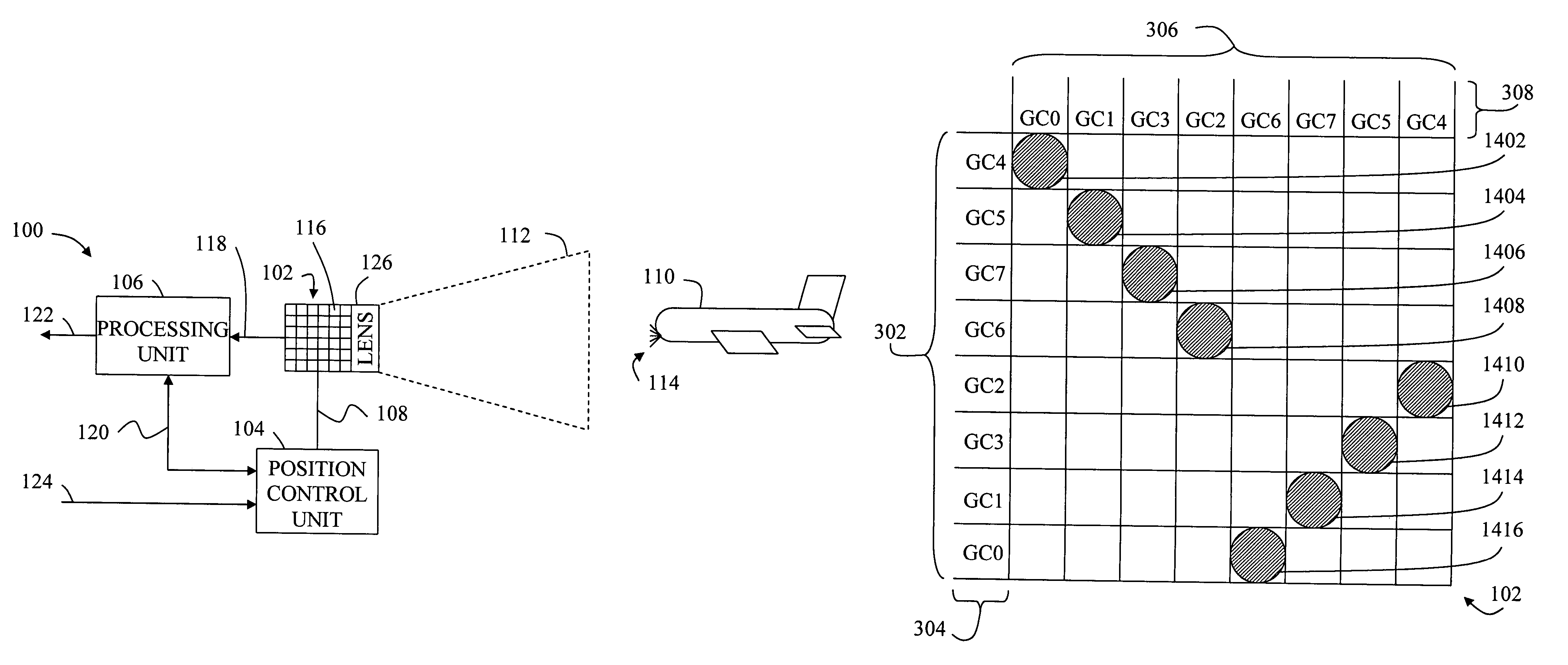
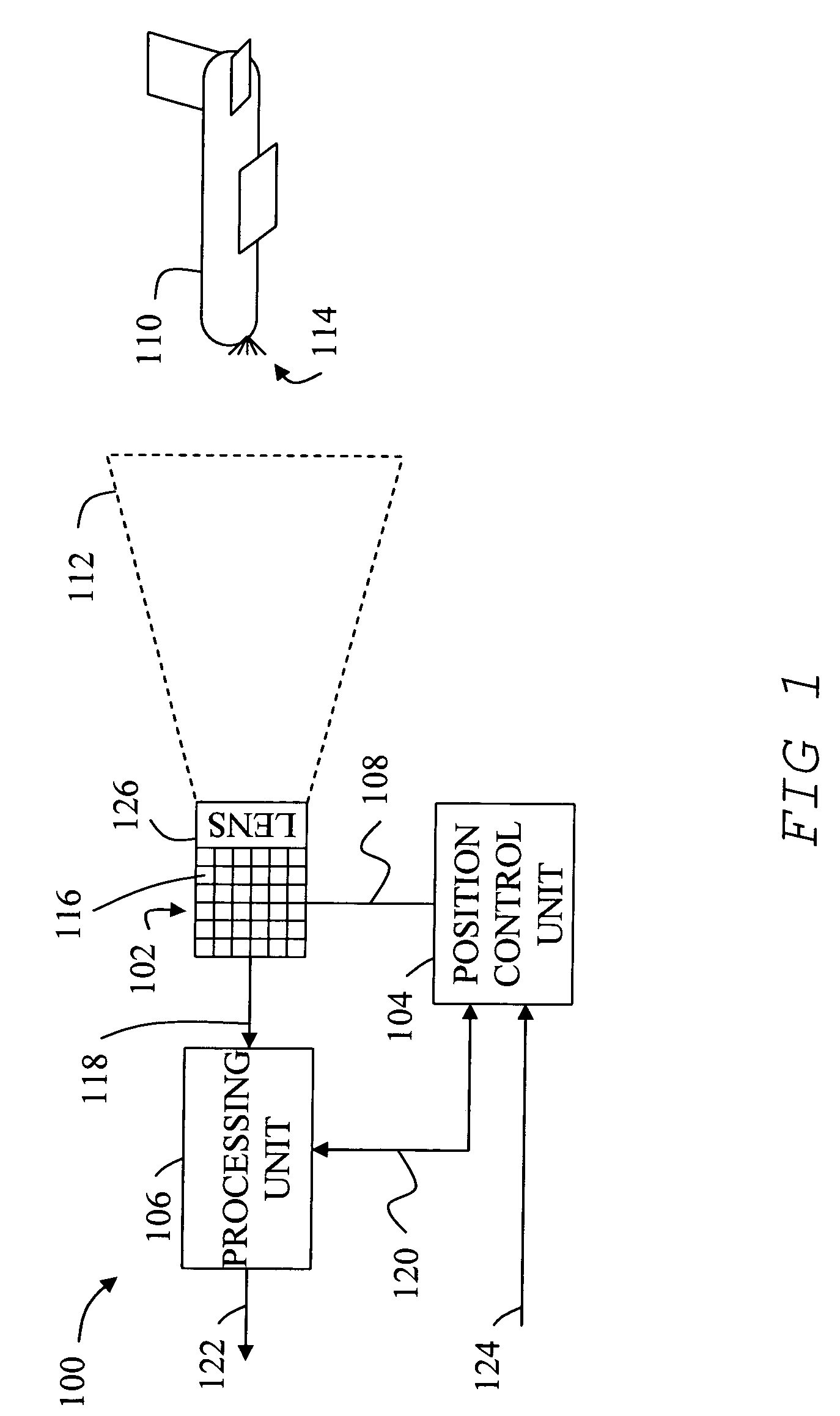
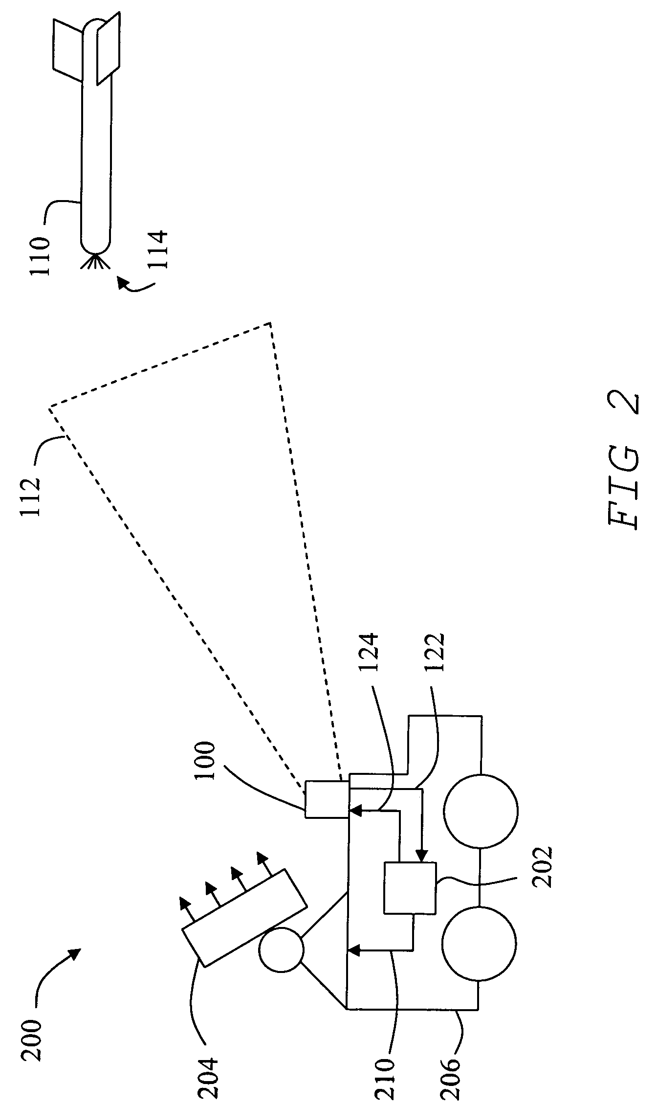
[0035]FIG. 1 shows one embodiment of an optical sensing system 100 including a Customized Focal Plane Array (CFPA) 102, a position control unit 104, a processing unit 106, and imaging optics 126. Position control unit 104 is operatively connected through a support mechanism 108 to CFPA 102 in order to control the angular position and elevation angle so that CFPA 102 can be positioned so that illumination from an object 110 within a field of view 112 will be focused and reimaged onto CFPA 102. Illumination from an object can include reflected or emitted light 114. For the purposes of this disclosure, light 114 can include any electromagnetic radiation that can be detected as disclosed including infrared to ultraviolet light. Further, support mechanism can include any mechanism for point...


PUM


Abstract

A plurality of optical sensing elements in an array where each element has a unique element address identifying the element location. Each element senses light and produces an element address signal in proportion to the intensity of the light sensed by the element. The element address signal corresponding to the highest intensity sensed by the array is asserted as an array output signal.

Description

TECHNICAL FIELD[0001]The present invention relates generally to optical sensors, and more particularly to a customized focal plane array with a Gray code output.RELATED ART[0002]Optical position sensors for use in Acquisition, Tracking, and Pointing (ATP) systems typically function by detecting light from a radiant or illuminated object using an optical sensor array including light sensitive detector elements. Electronic signals from the detector elements are processed to determine information about the object based on the detected light.[0003]The electronic output of an optical sensor array is typically digitized and can be arithmetically processed to determine the position of a radiant or reflective object based on a light pattern corresponding to an image of the object received by the sensor array. Additional processing algorithms may be required to compensate for sensor nonlinearities, background illumination, and other factors. This additional processing introduces latency that...

Claims


Application Information

Patent Timeline
Patent Type & Authority Patents(United States)
IPC IPC(8): G01J1/42
CPCF41G3/14F41G5/08G01S3/784
Inventor MUENTER, STEVEN E.HUNT, JON E.
Owner THE BOEING CO
Why Eureka
Try Eureka