
Video signal processing circuit, video display apparatus, and video display method

a video signal and display apparatus technology, applied in the field of video signal processing circuits, video display apparatuses, video display methods, can solve problems such as deficiency in this respect, complicating constitution and signal processing, etc., and achieve the effect of high contras

Active Publication Date: 2007-09-04
MAXELL HLDG LTD
View PDF29 Cites 18 Cited by
  • Summary
  • Abstract
  • Description
  • Claims
  • Application Information

AI Technical Summary

Benefits of technology

The present invention provides a video display apparatus that can produce a stable video with high contrast. The apparatus includes a video signal processing system that uses a gain control module and a correction module to adjust the brightness of the video signal. The gain control module adjusts the brightness of the video signal based on maximum and average luminance level information. The correction module then applies a gamma correction to the video signal based on the average luminance level. This results in a video display that has a consistent brightness level across different parts of the screen. The invention also includes a method for receiving multiple input video signals and adjusting the brightness of each signal using a gain control and gamma correction to produce an output video signal with a consistent brightness level.

Problems solved by technology

However, in the above-mentioned conventional art, there is a defect in this respect because, for example, gain control of a video signal is not associated with a luminance level.
In addition, calculation and analysis processing of a histogram are also required, which complicates the constitution and signal processing.

Method used


Image

  • Video signal processing circuit, video display apparatus, and video display method
  • Video signal processing circuit, video display apparatus, and video display method
  • Video signal processing circuit, video display apparatus, and video display method

Examples


first embodiment

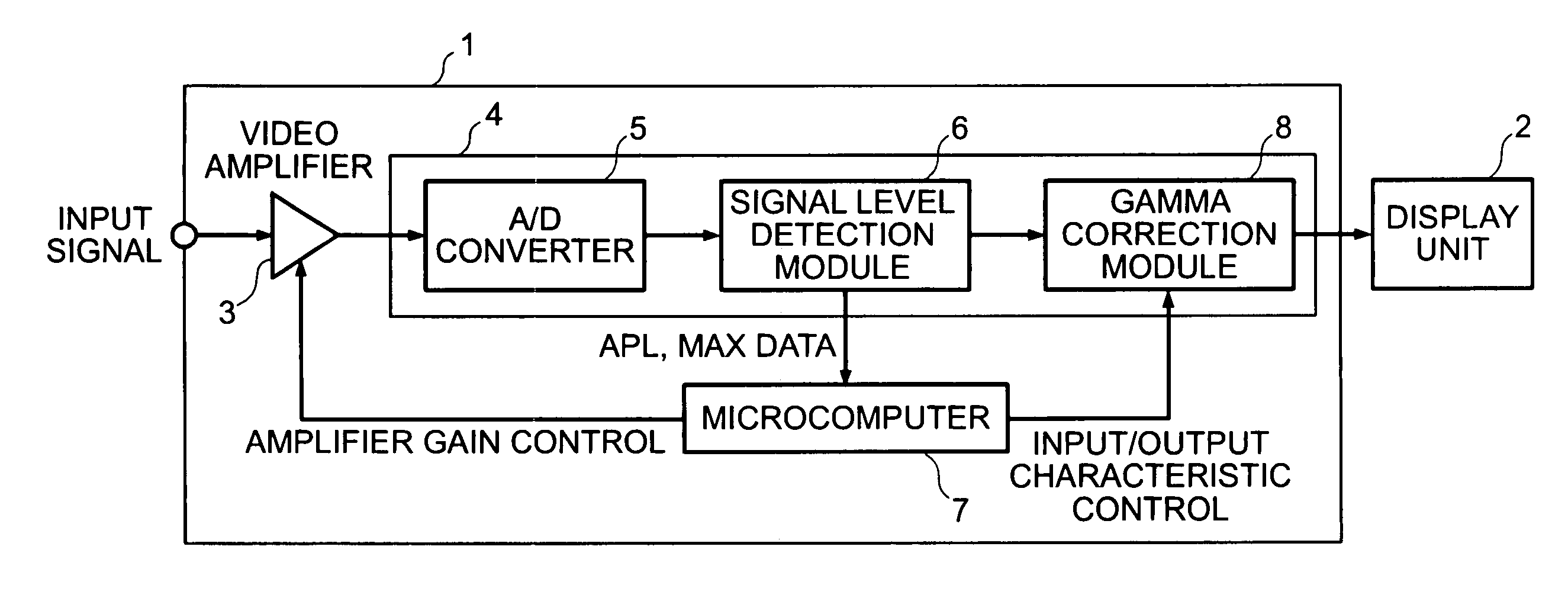
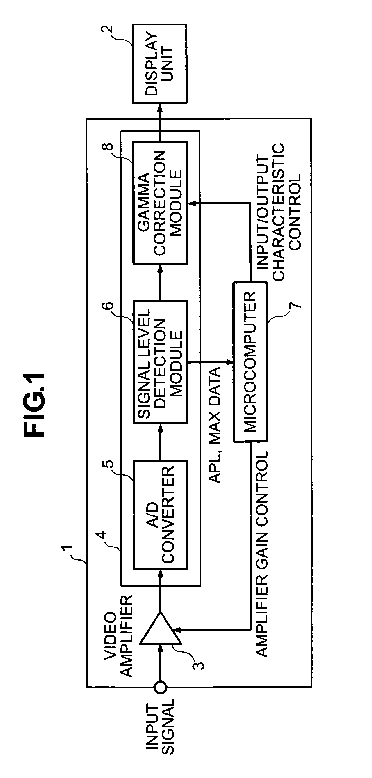
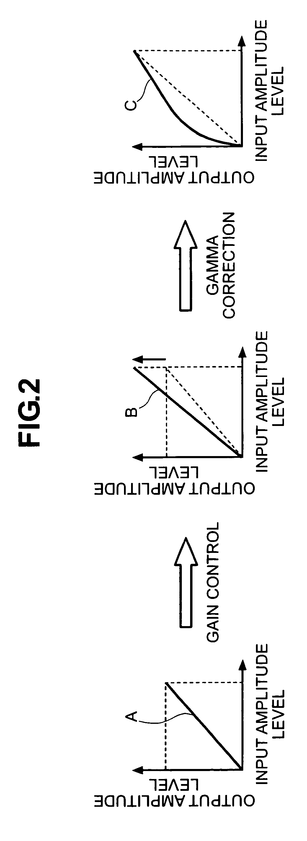
[0021]In the video amplifier 3, for example, an analog luminance signal of an input signal having input / output characteristics A (in the case of the first embodiment, analog luminance signal) is subjected to gain control according to a control signal from the microcomputer 7, and outputted as, for example, an analog luminance signal of input / output characteristics B. The analog luminance signal of input / output characteristics B is further subjected to A / D conversion and combined with a color signal to be a digital video signal. The digital video signal is corrected in input / output characteristics of a luminance signal thereof by the gamma correction module 8, and outputted as, for example, a digital video signal of input / output characteristics C. The control signal inputted to the video amplifier 3 is formed on the basis of both information of the first luminance area, to which a maximum luminance level of the luminance signal corresponds, and information of a second luminance area,...

second embodiment

[0035] since it is also possible to set an amplitude of an input video signal, which is inputted to the gamma correction module 30, to substantially a fixed value in the video display apparatus, gamma correction can be performed with high accuracy. In addition, a video in which color density is also secured can be displayed by control of the color control module 31. Further, since gamma correction can be performed in a state in which a maximum amplitude of a video signal is substantially matched with a dynamic range, contrast adjustment in a wide level becomes possible. Moreover, a stable video with a high contrast can be obtained by gamma correction according to brightness of a screen.

[0036]Note that, in the above-mentioned embodiments, concerning gain control of a luminance signal, gain control is performed for an analog luminance signal before A / D conversion. However, the present invention is not limited to this, and the gain control may be performed for a digital luminance signa...


PUM


Abstract

Embodiments of the invention provide a video display technique with which a stable video with a high contrast can be obtained according to brightness of a screen. In one embodiment, a video signal processing system for a video display apparatus which performs display on the basis of a video signal comprises a gain control module configured to provide a feedback signal based upon maximum luminance level information and average luminance level information of a luminance signal corresponding to the video signal, the feedback signal being used to control a gain of the luminance signal; and a correction module configured to apply a gamma correction based upon the average luminance level information to the video signal after the gain of the luminance signal has been controlled by the gain control module.

Description

CROSS-REFERENCES TO RELATED APPLICATIONS[0001]This application relates to and claims priority from Japanese Patent Application No. 2003-114527, filed on Apr. 18, 2003, the entire disclosure of which is incorporated herein by reference.BACKGROUND OF THE INVENTION[0002]The present invention relates to a technique for displaying a video on the basis of a television signal or a video signal inputted from a personal computer or the like.[0003]As a conventional art related to the present invention, there is one described in JP-A-8-317250 (Patent Literature 1). In the laid-open patent application, there is described a technique for calculating an APL and a histogram from an inputted video signal to analyze them, expanding ranges of a minimum level and a maximum level of the video signal to increase a gamma value of input / output characteristics corresponding to the vicinity of the APL, and increasing a contrast ratio of a displayed picture.[0004]In a video display apparatus using a fixed pi...

Claims


Application Information

Patent Timeline
Patent Type & Authority Patents(United States)
IPC IPC(8): H04N5/14G06K9/40G09G5/02H04N5/202H04N5/52H04N5/57G06T5/00
CPCH04N5/202E06B7/367E06B3/02E05Y2800/41
Inventor OHYAMA, TOSHIAKIAOKI, HIROSHIHASEGAWA, RYO
Owner MAXELL HLDG LTD
Learn More