
Optical pickup actuator and optical disk drive using the same and method

a technology of optical disk drive and actuator, applied in the direction of data recording, instruments, disposition/mounting of heads, etc., can solve the problems of reproducing data, unable to create precise, and unable to accurately capture data, so as to improve the sensitivity of actuation in focusing, tracking and tilt directions, and reduce the space limitation for installation.

Active Publication Date: 2007-09-04
TS OPTICS CORP
View PDF5 Cites 9 Cited by
  • Summary
  • Abstract
  • Description
  • Claims
  • Application Information

AI Technical Summary

Benefits of technology

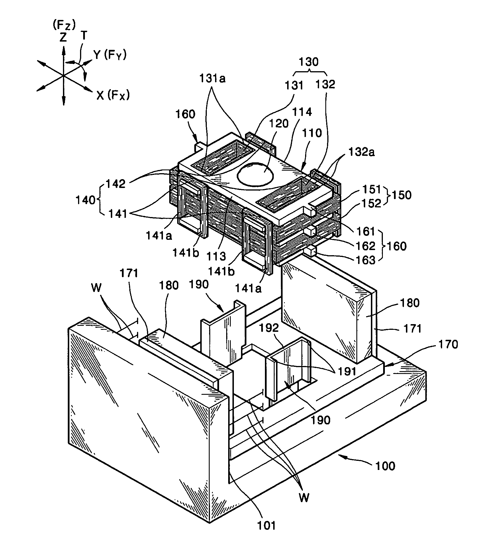
"The present invention provides an optical pickup actuator and an optical pickup drive with improved sensitivity and reduced space limitation. The actuator includes a blade holding an objective lens and supported on a base by a plurality of suspension wires, a magnetic element positioned on the base, and a coil positioned horizontally on the blade. The coil is divided into a plurality of subcoils that are vertically separated from one another. The actuator also includes a stopper to prevent the blade from colliding with the base. The optical pickup drive includes a spindle motor for rotating the disc, an optical pickup for recording and reproducing information, and an optical pickup actuator for controlling the position of the objective lens. The actuator includes a blade holding the objective lens and supported on a base by a plurality of suspension wires, a magnetic element positioned on the base, and a coil positioned horizontally on the blade. The actuator also includes a third coil positioned to surround the sides of the blade. The invention provides a solution for improving the performance of optical pickup actuators and optical pickup drives."

Problems solved by technology

Otherwise, it is not possible to create a precise light spot on the disc, which may cause an error in recording data on, or reproducing data from, the disc.
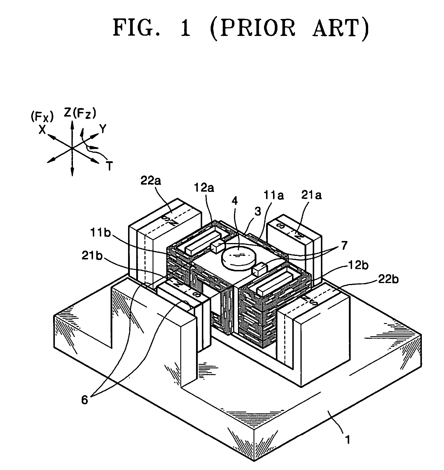
This poses a limitation in that the optical pickup actuator needs to be designed to avoid interference with a spindle motor (not shown) for rotating the disc.

Method used


Image

  • Optical pickup actuator and optical disk drive using the same and method
  • Optical pickup actuator and optical disk drive using the same and method
  • Optical pickup actuator and optical disk drive using the same and method

Examples


Embodiment Construction

[0047]Reference will now be made in detail to the embodiments of the present invention, examples of which are illustrated in the accompanying drawings, wherein like reference numerals refer to the like elements throughout. The embodiments are described below to explain the present invention by referring to the figures.

[0048]Referring to FIG. 3, a base 54 having a spindle motor 51 and an optical pickup 53 mounted thereon is positioned on a mainframe 50. The base 54 is supported on a pair of guide shafts 52 positioned in a radial direction of a disc D on the mainframe 50.

[0049]The spindle motor 51 rotates the disc D, and a turntable 55 on which the disc D rests is coupled with a rotary axis of the spindle motor 51. The optical pickup 53 records information on, or reproduces information from, the disc D by emitting light onto the disc D through the objective lens 56. The optical pickup 53 is positioned on the base 54 to reciprocate along the guide shaft 52 in a radial direction of the ...


PUM

PropertyMeasurementUnit
electromagnetic forceaaaaaaaaaa
polarityaaaaaaaaaa
electromagnet forceaaaaaaaaaa

Abstract

An optical pickup actuator and optical disc drive using the same. The optical pickup actuator includes a blade holding an objective lens and supported on a base by a plurality of suspension wires so that it is elastically movable, a magnetic element positioned on the base, and a coil positioned horizontally on the blade to generate electromagnetic force in a focusing direction and / or a tilting direction through interaction with the magnetic element. The coil is divided into a plurality of subcoils separated vertically from one another.

Description

CROSS-REFERENCE TO RELATED APPLICATION[0001]This application claims the benefit of Korean Patent Application No. 2003-35305, filed on Jun. 2, 2003, in the Korean Intellectual Property Office, the disclosure of which is incorporated herein by reference.BACKGROUND OF THE INVENTION[0002]1. Field of the Invention[0003]The present invention relates to an optical disk drive, and more particularly, to an optical disk drive including an optical pickup actuator employing a Lorenz force generated in a coil by electromagnetic induction.[0004]2. Description of the Related Art[0005]In general, an optical disk drive writes information by scanning light onto a disc that is a recording medium or reads information from the disc. The optical disk drive includes a spindle motor that rotates a disc and an optical pickup that records information on, or reproduces information from, a recording surface of the disc by emitting light onto the recording surface.[0006]Typically, an optical pickup has an actua...

Claims


Application Information

Patent Timeline
Patent Type & Authority Patents(United States)
IPC IPC(8): G11B7/00G11B7/08G11B7/09G11B7/095
CPCG11B7/0932G11B7/0933G11B7/0935G11B7/08
Inventor CHO, WON-IKRYOO, BYUNG-RYULPARK, YOUNG-PILPARK, NO-CHEOL
Owner TS OPTICS CORP
Learn More