Rotary type hinge device for portable wireless terminal

a portable wireless terminal and hinge device technology, applied in the direction of hinges, wing accessories, manufacturing tools, etc., can solve the problems of limited miniaturization of flip type terminals, keypad malfunction, and limited miniaturization of bar type terminals

Inactive Publication Date: 2007-09-11
SAMSUNG ELECTRONICS CO LTD
View PDF16 Cites 30 Cited by
  • Summary
  • Abstract
  • Description
  • Claims
  • Application Information

AI Technical Summary

Benefits of technology

[0013]Therefore, the present invention has been achieved in view of the above problem, and it is an object of the present invention to provide a hinge de

Problems solved by technology

In the case of the bar type terminals, there is a disadvantage that a keypad, as data input means, is always exposed to accidental misuse and damage that may cause the keypad to malfunction.
In addition, the bar type terminals are limited in extent of their miniaturization due to a technologically required minimal distance between the receiver and transmitter modules.
However, the flip type terminals are still limited in their miniaturization due to a technologically required minimal distance between receiver and transmitter modules thereof.
Although functions of the portable wireless terminals have rapidly expanded as mobile services have become increasingly diversified, the conventional hinge device has not varied its function of simply causing the flip cover or folder of the portable wireless

Method used


Image

  • Rotary type hinge device for portable wireless terminal
  • Rotary type hinge device for portable wireless terminal
  • Rotary type hinge device for portable wireless terminal

Examples


Embodiment Construction

[0039]Preferred embodiments of the present invention will be described in detail with reference to the annexed drawings. In the drawings, the same or similar elements are denoted by the same reference numerals even though they are depicted in different drawings. In the following description, a detailed description of known functions and configurations incorporated herein will be omitted when it may make the subject matter of the present invention rather unclear. Also, the terms used in the following description are terms defined taking into consideration the functions obtained in accordance with the present invention. The definitions of these terms should be determined based on the whole content of this specification and may be changed at the option of a user or common practice.

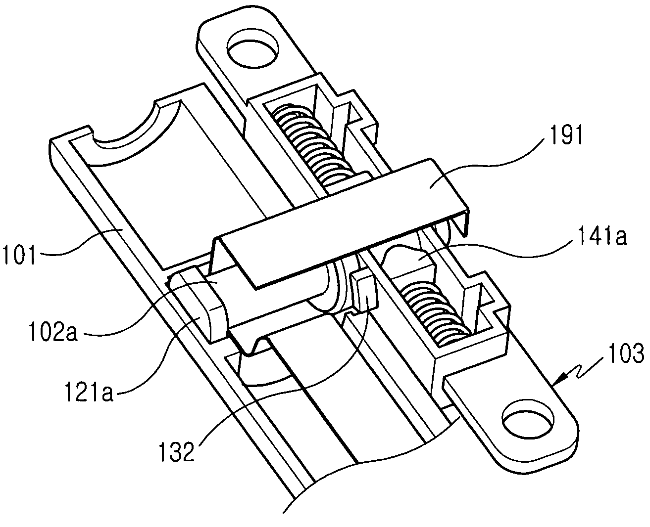
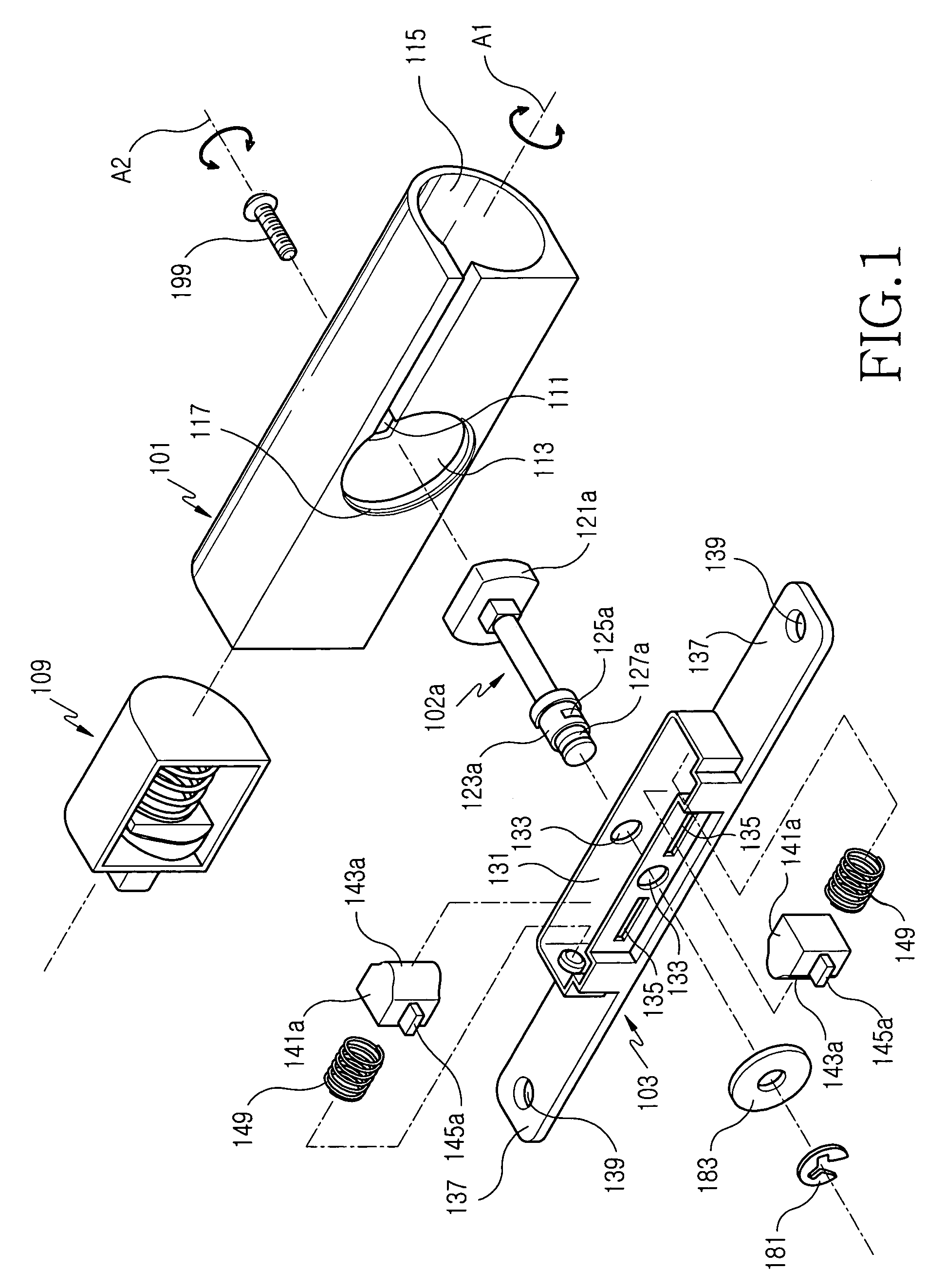
[0040]FIG. 1 is an exploded perspective view illustrating a rotary type hinge device of a portable wireless terminal in accordance with a preferred embodiment of the present invention. As shown in FIG. 1, the...


PUM


Abstract

A rotary type hinge device, installed between a terminal body and a folder of the portable wireless terminal. The hinge device has a first rotation axis for opening and closing operations of the terminal body and folder, and a second rotation axis extending perpendicular to the first rotation axis to be rotated relative to the first rotation axis. The hinge device is adapted to rotate the folder about the second rotation axis in a state wherein the folder and terminal body are opened. The hinge device comprises a first hinge housing coupled to the terminal body to rotate about the first rotation axis; a main shaft having its one end fixed to the inner peripheral surface of the first hinge housing and the other end thereof protruding outwardly from one side of the first hinge housing; and a second hinge housing rotatably coupled to the other end of the main shaft protruded outwardly from the first hinge housing and adapted to rotate about the second rotation axis. The second hinge housing is fixed to the folder. The rotary type hinge device constructed as stated above enables the biaxial rotation of the folder, thereby allowing the reversal of front and rear surfaces thereof. Therefore, the portable wireless terminal has advantages that the change of the specification or design thereof is easy and its convenience of use is increased.

Description

[0001]This application claims priority to an application entitled “ROTARY TYPE HINGE DEVICE FOR PORTABLE WIRELESS TERMINAL”, filed in the Korean Industrial Property Office on Apr. 8, 2003 and assigned Ser. No. 2003-22098, the contents of which are hereby incorporated by reference.BACKGROUND OF THE INVENTION[0002]1. Field of the Invention[0003]The present invention relates to a hinge device for a portable wireless terminal, and more particularly to a rotary type hinge device of biaxial rotation, which enables the reversal of front and rear surfaces of a folder, opened away from a terminal body of a portable wireless terminal, while rotating relative to the terminal body.[0004]2. Description of the Related Art[0005]Generally, portable wireless terminals are classified into bar type terminals, flip type terminals and folder type terminals, in accordance with an external form thereof.[0006]The bar type terminals are configured so that a single body housing thereof is provided with data ...

Claims


Application Information

Patent Timeline
IPC IPC(8): E05D3/10H04B1/38E05D11/10H04M1/02
CPCH04M1/0212E05D3/10E05D11/105E05D11/1064Y10T16/5472H04M1/0218E05Y2900/606H04B1/38
Inventor KIM, JAE-SHIK
Owner SAMSUNG ELECTRONICS CO LTD
Why Eureka
Try Eureka