Bicycle crank assembly

a technology of pedal cranks and cranks, which is applied in the direction of mechanical control devices, instruments, process and machine control, etc., can solve the problems of high production cost of joints between components, undesirable stress concentration, and increase the weight of the structure, so as to save a considerable amount of overall weight, simplify the assembly procedure for users, and keep the strength in the polygonal length of the crank

Active Publication Date: 2007-09-11
BEARCORP
View PDF23 Cites 27 Cited by
  • Summary
  • Abstract
  • Description
  • Claims
  • Application Information

AI Technical Summary

Benefits of technology

[0010]A locking fastener member is provided for each crank arm and is engageable with the corresponding coupling end of the spindle. The wedging members may either be split bushings or sets of wedge-shaped shims circumferentially joined together by connecting webs. If the wedging member is formed of a set of tapered shims the locking member bears against the socket and draws the coupling end of the spindle into the coupling cavity of the socket. With this construction advancement of the locking member causes the circumferential spacings between the tapered shims to be reduced by deforming the connecting webs joining them together as the shims are forced toward the narrow end of the socket. If the wedging member is a split bushing the locking member bears against the widest end of the wedging member and forces it onto the tapered spindle. With this construction, advancement of the wedging member causes the gap formed at the radial split in the wedging member to increase, thus compressing the wedging member between the spindle and the interior surface of the corresponding socket.
[0025]A further advantage of the two-piece crank assembly is that it uses a single lock bolt. Conventional crank sets use anywhere from two to six lock bolts to assemble the crank arms together. A reduction in the number of bolts simplifies the assembly procedure for the user and reduces weight.

Problems solved by technology

The joints between the components are usually expensive to produce and inherently add weight to the structure.
Also, there are undesirable stress concentrations in most conventional bicycle pedal crank assembly designs.
The conventional spline system in which there is no radial gap in the socket wall has inherent problems.
While this firm, structurally secure connection provides excellent force transmission characteristics and reduces stress in the bicycle pedal crank assembly components, disassembly of the crank assemblies is very difficult, even for experienced users.
That is, the spline fit is so tight that it is extremely difficult to remove either crank arm from the spindle to repair or replace components parts of the bicycle pedal crank assembly, or of bicycle parts that are engaged by the assembly.
However, the increased tolerance in fit results in the cyclical pedal force producing wear upon both the sockets in the crank arms, and also the splines on the spindle.
However, crank set designs that employ pinch bolts remove a substantial portion of the structural strength of material of each crank arm end surrounding the socket.
This results from the radial split in the socket area of the crank arm that is already under high stress.
“Pinch” bolt designs are also unpopular with many riders, both due to their physical appearance, and because of injuries that can result to the user while riding due to the additional mass at the coupling end of the crank arm necessary to house the pinch bolts.

Method used


Image

  • Bicycle crank assembly
  • Bicycle crank assembly
  • Bicycle crank assembly

Examples


Embodiment Construction

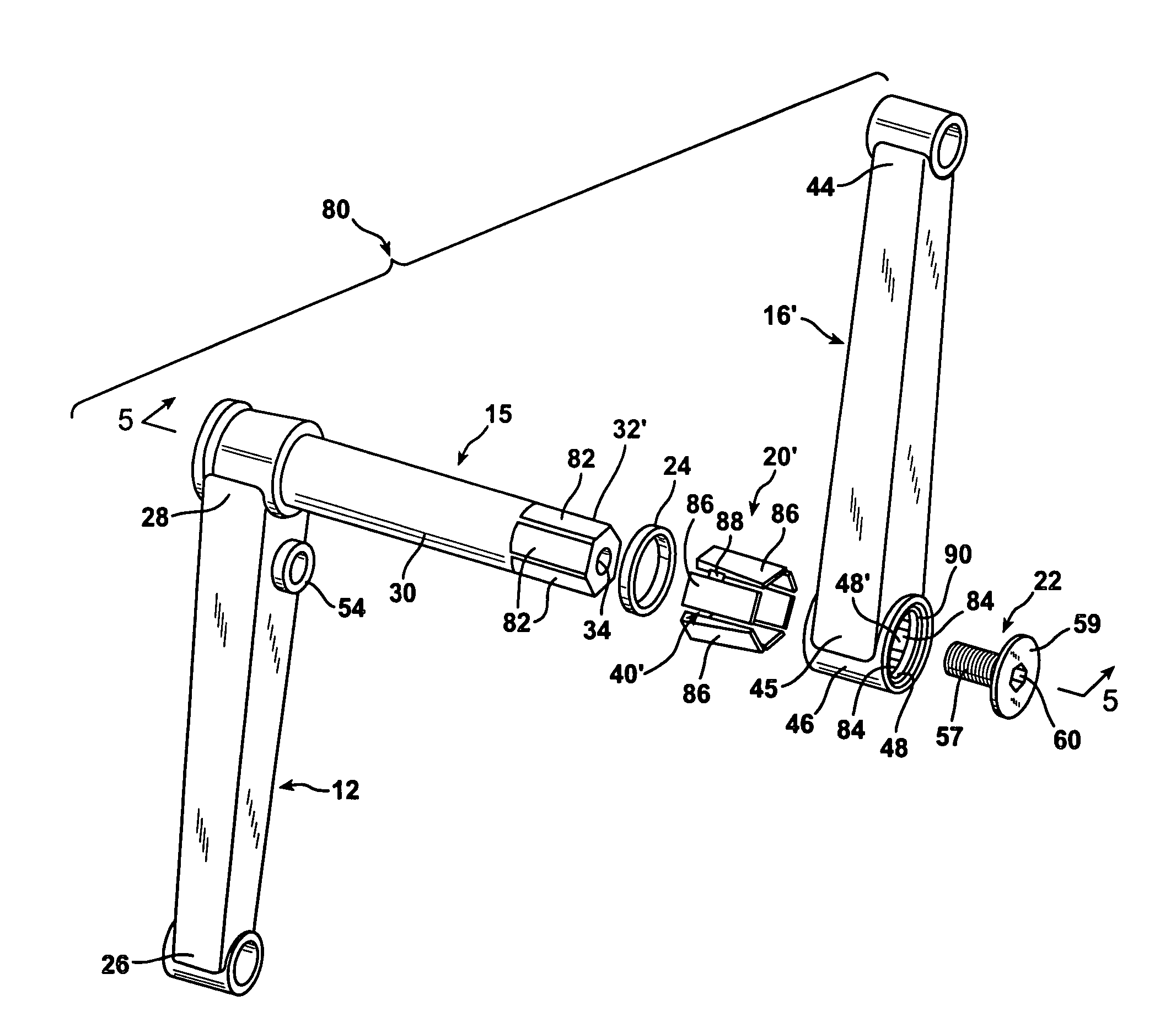
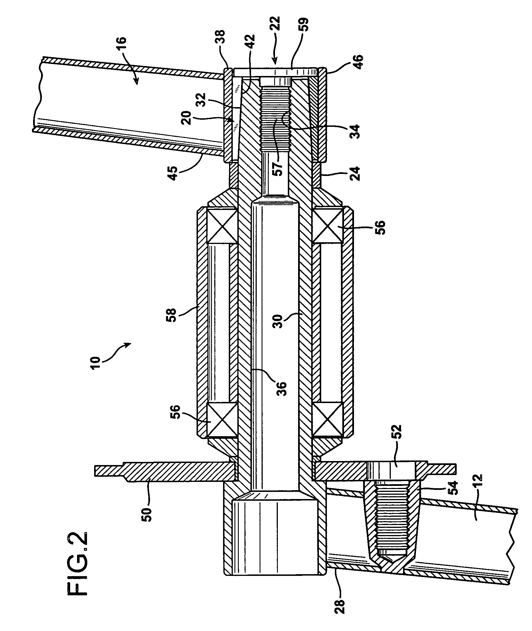
[0050]FIGS. 1 and 2 illustrate a two-piece bicycle sprocket crank assembly 10 in which the first crank arm 12 and the axle or spindle 14 are formed together as a unitary metal structure, and in which the second crank arm 16 is formed as separate structure. The two crank arms 12 and 16 and the spindle 14 are formed of 4130 chromium-molybdenum steel alloy. The first crank arm 12 is permanently joined to the spindle 14, while the second crank arm 16 is removable from the spindle 14. In addition to the two major structural components, the bicycle sprocket crank assembly 10 is also comprised of a first, single, metal wedging sleeve 20, a first, single, metal threaded fastener 22, and a metal stop spacer 24.

[0051]The first crank arm 12 has a pedal end 26 at which a bicycle pedal is mounted in a conventional fashion, and an opposing axle end 28. The first crank element or arm 12 is radially oriented relative to the spindle 14 which extends axially therefrom at the axle end 28 of the crank ...


PUM


Abstract

A bicycle sprocket crank assembly is comprised of first and second crank arms joined to a spindle. One of the crank arms and the spindle may be fabricated as a unitary structure, or both cranks arms may be formed as separate structures and joined together. In either case the spindle has at least a first coupling end with an internally tapped axial bore defined therein and the second crank arm forms at least a first socket at its axle end. At least a first wedging sleeve is provided and is disposed about the first coupling end of the spindle. The first wedging sleeve conforms to the shapes of both the first coupling end of the spindle and the hollow cavity in the first socket. Either the coupling end of the spindle or the hollow cavity is axially tapered, and the wedging sleeve is tapered to match. The wedging sleeve is split in an axial direction, so that as the first socket is drawn onto the first coupling end of the spindle, the wedging sleeve is increasingly forced in between the inner radial surface of the hollow cavity of the socket and the outer radial surface of the coupling end of the spindle.

Description

BACKGROUND OF THE INVENTION[0001]1. Field of the Invention[0002]The present invention relates to bicycle pedal crank assemblies utilized to transmit power applied manually on the pedals of a bicycle to turn the bicycle wheels.[0003]2. Description of the Prior Art[0004]Many bicycles, including most BMX bicycles, employ bicycle crank sets that are comprised of three major structural components. These components include two “handed” crank arms, and one central, axial, connecting crank shaft, which is an axle and is also referred to as a spindle. To function properly, the assembled components of a bicycle pedal crank assembly must be torsionally stiff so that the relative orientation of the crank arms can be maintained to transmit all of the force applied into the pedaling drive. The joints between the components are usually expensive to produce and inherently add weight to the structure. Also, there are undesirable stress concentrations in most conventional bicycle pedal crank assembly...

Claims


Application Information

Patent Timeline
Patent Type & Authority Patents(United States)
IPC IPC(8): B62M3/00G05G1/30
CPCB62M3/00B62M3/003Y10T74/2165Y10T74/2164
Inventor FRENCH, GEORGE
Owner BEARCORP
Why Eureka
Try Eureka