Controller of internal combustion engine

a controller and internal combustion engine technology, applied in the direction of electric control, combustion engine, speed sensing governor, etc., can solve the problems of low robustness of air flow rate control accuracy and the inability of control methods to exercise air flow rate control

Inactive Publication Date: 2007-09-11
HITACHI LTD +1
View PDF4 Cites 8 Cited by
  • Summary
  • Abstract
  • Description
  • Claims
  • Application Information

AI Technical Summary

Benefits of technology

[0017]As indicated by the configuration described above, the internal combustion engine controller of the present invention comprises a first throttle opening computing means for computing a throttle opening by exercising feedback control (F / B control) in accordance with the actual air flow rate, target air flow rate, and other operating conditions and a second throttle opening computing means for computing a throttle opening by exercising feed-forward control (F / F control) in accordance with the target air flow rate and other operating conditions. Therefore, the internal combustion engine controller of the present invention can improve the air flow rate calculation response and convergence, reduce the exhaust gas emission, and provides improved torque response without being affected by various environmental changes or sensor, actuator, and other component variations.
[0039]As indicated by the configuration described above, the internal combustion engine controller of the present invention corrects the target air flow rate with a correction amount (manipulated variable) that is used to compute (by means of air-fuel ratio feedback control) the correction amount for the target air flow rate in accordance with a signal from an A / F sensor or other exhaust gas component detection means. It is therefore possible to calculate a target air flow rate with increased accuracy and compute a target throttle opening.

Problems solved by technology

Therefore, the transmission characteristic of the fuel injection side is smaller than that of the air side because time is merely wasted by intermittent combustion.
However, this control method cannot exercise air flow rate control if the air flow sensor is faulty because it computes the target throttle opening in accordance with the deviation between the actual air flow rate and target air flow rate.
However, since this control method does not detect the actual air flow rate, it cannot properly respond, for instance, to air density changes at a high altitude and exhibits low robustness for air flow rate control accuracy in relation to various environmental changes such as throttle control sensor and actuator characteristic variations.

Method used


Image

  • Controller of internal combustion engine
  • Controller of internal combustion engine
  • Controller of internal combustion engine

Examples


first embodiment

[0088]The control program to be written into the ROM 52 of the EPU 50 will now be described.

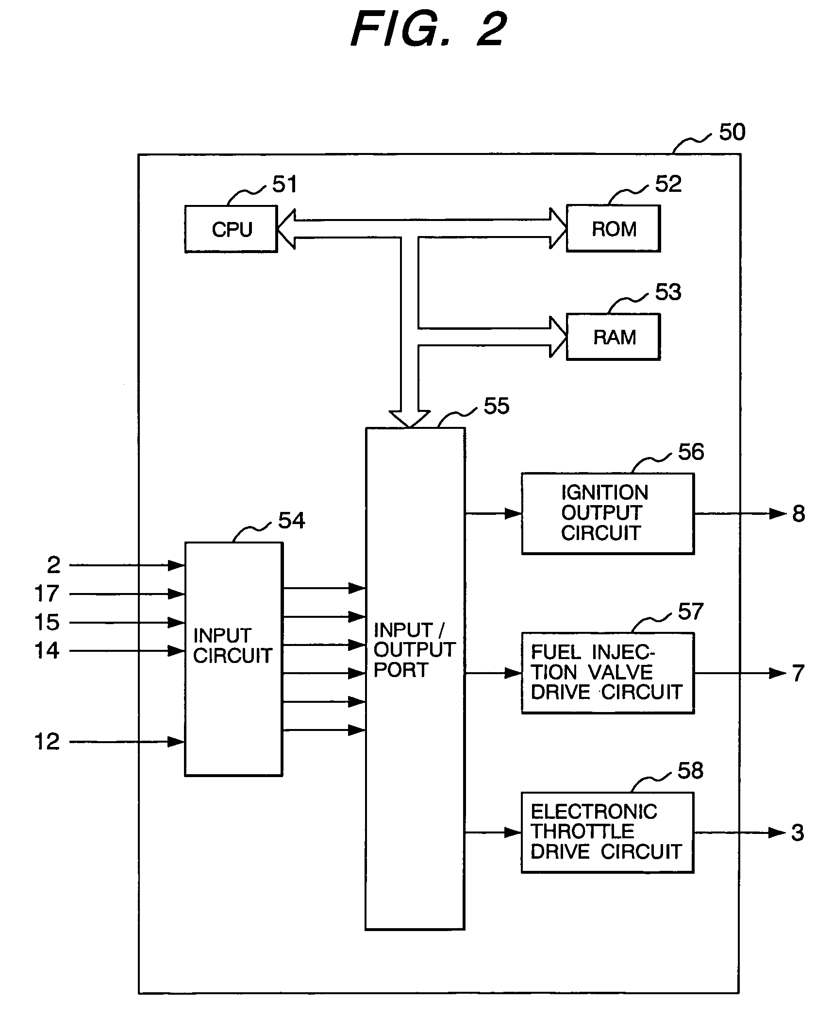
[0089]FIG. 3 is a control block diagram illustrating the overall control operation that the EPU 50 shown in FIG. 2 performs in accordance with a first embodiment. The major portion of a fuel-based, torque-on-demand control is shown in FIG. 3.

[0090]This control comprises a target torque computing section 61, a fuel injection quantity computing section 62, a fuel injection quantity correction section 63, a target equivalence ratio computing section 64, a target air flow rate computing section 65, an actual air flow rate computing section 66, a target throttle opening computing section 67, and a throttle opening control section 68.

[0091]The target torque computing section 61 computes a target torque TgTc from an accelerator opening Apo and an internal computer combustion engine rotating speed Ne. The fuel injection quantity computing section 62 operates based on the target torque TgTc to compute...

second embodiment

[0109]The control block of an internal combustion engine controller according to a second embodiment of the present invention will now be described in detail. FIG. 12 is a control block diagram of the second embodiment that illustrates the overall control of the EPU 50 shown in FIG. 2. The major portion of a fuel-based, torque-on-demand control is shown in FIG. 12.

[0110]The target torque computing section 61, fuel injection quantity computing section 62, fuel injection quantity correction section 63, target equivalence ratio computing section 64, target air flow rate computing section 65, actual air flow rate computing section 66, and target throttle opening computing section 67 within the control block of the second embodiment are the same as their counterparts described in Sections 1 to 7, respectively, under the first embodiment and will not be described again.

8. Throttle Opening Control Section

[0111]FIG. 13 illustrates the throttle opening control section 68. As indicated in FIG...

third embodiment

[0113]The control block of an internal combustion engine controller according to a third embodiment of the present invention will now be described in detail. The control block of the third embodiment differs from that of the first embodiment, which is shown in FIG. 3, in that the target air flow rate TgTp for use in feedback control is filtered in relation to a feed-forward control target value in the target throttle opening computing section 67. The filter characteristic will be described in detail later. However, it is a response characteristic between the target throttle opening and in-cylinder actual air flow rate that is computed by means of feed-forward control in the target air flow rate computing section 65. The purpose is to exercise feedback control to compensate for the steady-state deviation.

[0114]The target torque computing section 61, fuel injection quantity computing section 62, fuel injection quantity correction section 63, target equivalence ratio computing section ...


PUM


Abstract

An internal combustion engine controller, is used with a fuel-based torque-on-demand control type, multi-cylinder, direct-injection internal combustion engine, to provide an air flow rate control that excels in response and convergence. The internal combustion engine controller includes a section for computing a target throttle opening from operating conditions, which in turn includes a first computing section for determining a target throttle opening by feedback control in accordance with operating conditions including an intake air flow rate; a second computing section for determining a target throttle opening by feed-forward control in accordance with operating conditions; and a third computing means for determining a target throttle opening based on the target throttle opening value determined by the first computing means and the second computing means.

Description

FIELD OF THE INVENTION[0001]The present invention related to internal combustion engine controllers, and more particularly to an internal combustion engine controller for accurately adjusting the air flow rate by controlling the air flow rate with an electronic control valve.BACKGROUND OF THE INVENTION[0002]In recent years, worldwide efforts have been made to provide increased energy savings. In the field of automotive technology, the development of a fuel-efficient internal combustion engine has been required for energy saving purposes. The most conspicuous internal combustion engine meeting such a demand is a lean-burn internal combustion engine. In particular, an in-cylinder fuel injection internal combustion engine, which is a lean-burn internal combustion engine, injects fuel directly into a cylinder to stratify an air-fuel mixture, thereby making it possible to achieve combustion at an air-fuel ratio of higher than 40 and reduce the pump loss.[0003]In a lean-burn in-cylinder f...

Claims


Application Information

Patent Timeline
Patent Type & Authority Patents(United States)
IPC IPC(8): F02D31/00F02D41/00F02D11/10F02D41/14
CPCF02D11/105F02D41/0002F02D41/1401F02D41/18F02D41/222F02D2011/102F02D2041/0017F02D2041/141F02D2041/1434F02D2250/18Y02T10/42Y02T10/40
Inventor NAKAGAWA, SHINJIOOSUGA, MINORUNAGANO, MASAMINEMOTO, MAMORUHORI, TOSHIO
Owner HITACHI LTD
Why Eureka
Try Eureka