
Inflator

a technology of inflator and airbag, which is applied in the direction of pedestrian/occupant safety arrangement, vehicle components, vehicular safety arrangements, etc., can solve the problems of hazardous inhalation of particulates by occupants of vehicles after airbag activation, and achieve the effect of optimizing efficiency, reducing airbag inflator size, weight and cos

Inactive Publication Date: 2007-09-11
JOYSON SAFETY SYST ACQUISITION LLC
View PDF115 Cites 48 Cited by
  • Summary
  • Abstract
  • Description
  • Claims
  • Application Information

AI Technical Summary

Benefits of technology

[0007]The solution to the problem of reducing airbag inflator size, weight, and cost, and optimizing efficiency, in accordance with the present invention, is predicated on the concept that it is possible to obviate the need for a filter by instead providing a baffle system that routes the gases for cooling and slag deposition throughout an associated flow buffer.
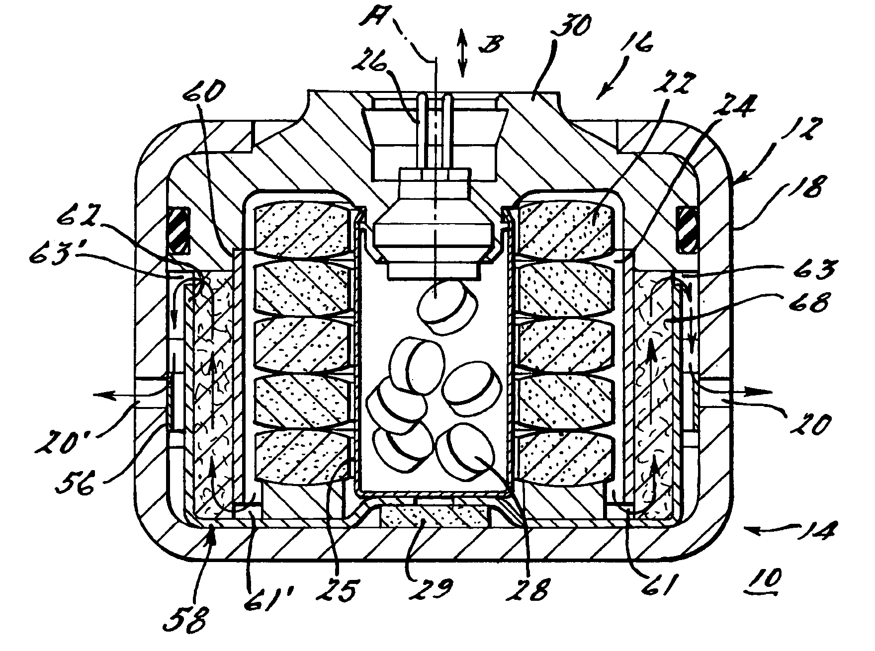
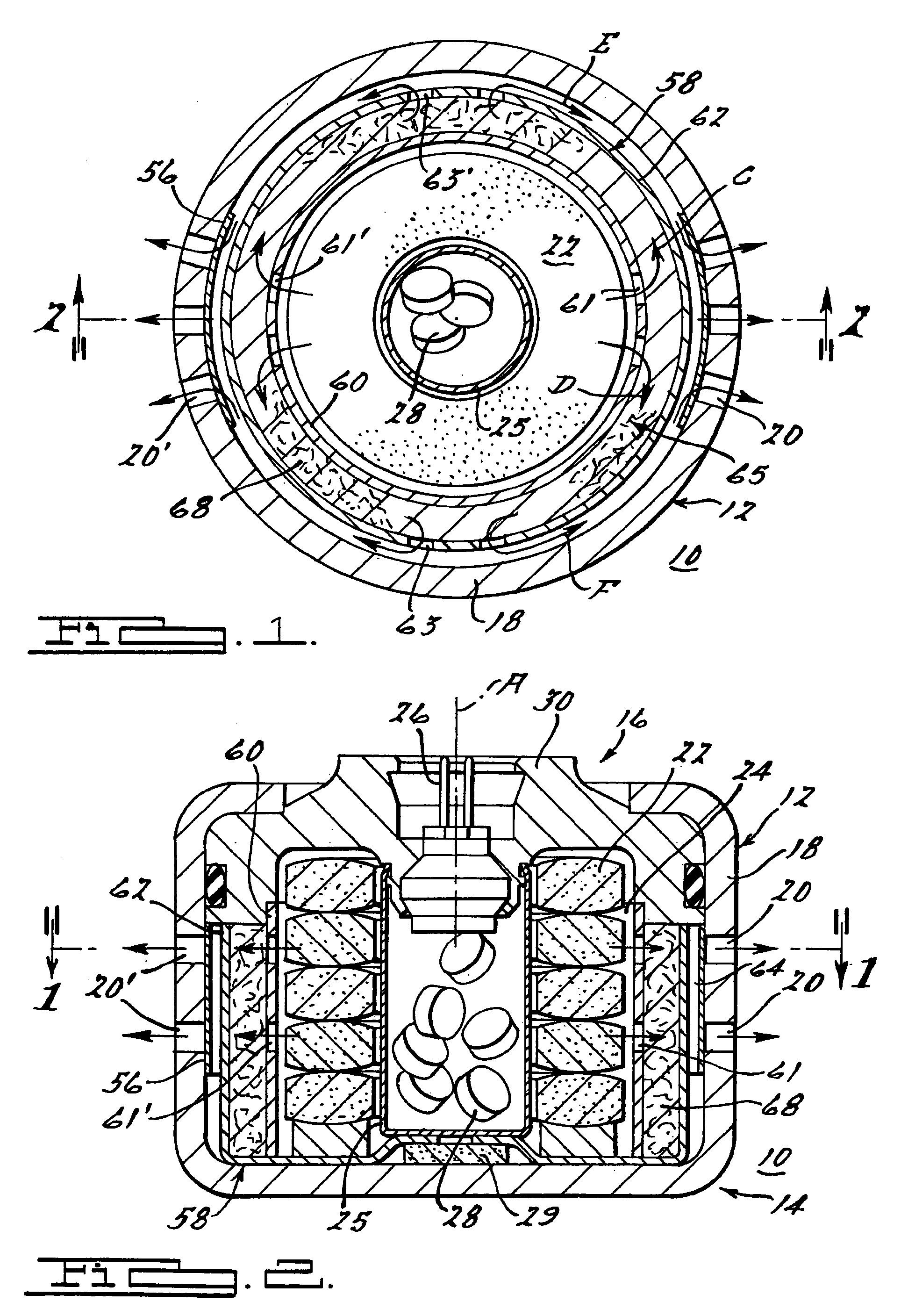
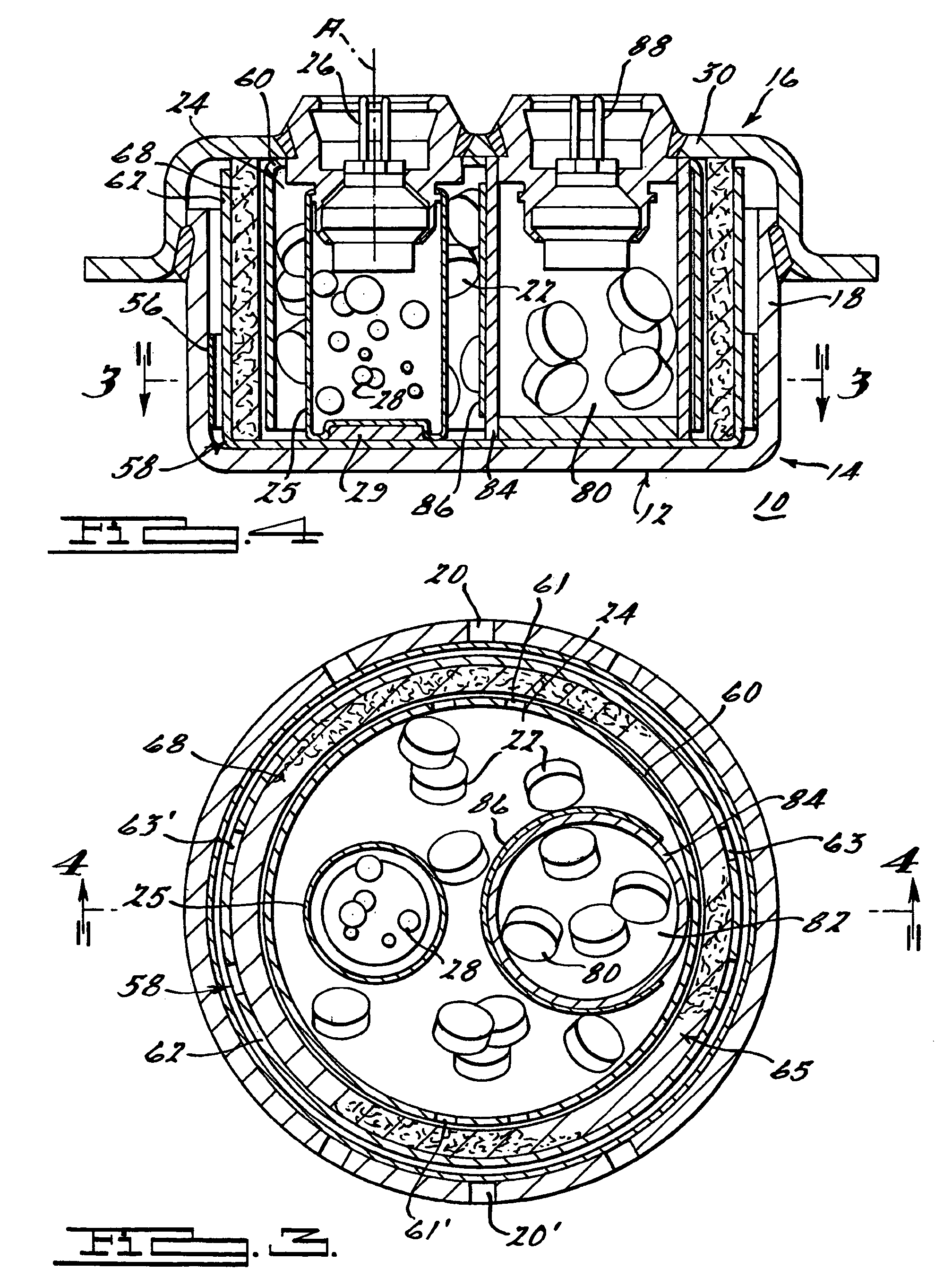
[0008]The present invention provides an inflator for a vehicle occupant restraint system. The inflator includes a cylindrical outer wall having a longitudinal axis and a first opening formed therealong for enabling fluid communication between an interior of the inflator and an exterior of the inflator. A first inflation fluid source or at least one inflation fluid source is positioned within the outer wall. A baffle system is intermediate of or fluidly interposed between the first inflation fluid source and the outer wall for conveying inflation fluid between the first inflation fluid source and the outer wall, and for cooling the inflation fluid. A second opening enables fluid communication between the first inflation fluid source and the baffle system, and a third opening enables fluid communication between the baffle system and the outer wall. The first opening facilitates overall radial flow from the second opening along the inner baffle.
[0009]In a first embodiment, the baffle system includes an inner baffle and an outer baffle concentrically arranged about the outer wall longitudinal axis to form a plenum therebetween. In addition, the outer baffle is positioned radially inward of the housing outer wall to form a plenum extending between the outer wall and the outer baffle. An expanded metal mesh buffer may be positioned in the plenum between the inner and outer baffles. Openings enabling fluid communication between the baffle system and the exterior of the baffle system, any openings provided within the baffle system, and the opening enabling fluid communication between the interior and exterior of the inflator housing are cooperatively positioned to direct the flow of an inflation through the baffle system in directions substantially parallel to a plane perpendicular to the longitudinal axis and / or substantially parallel to the longitudinal axis.
[0011]It is believed that the advantages attendant to the inflator formed in accordance with the present invention will translate into similar benefits with regard to the airbag module and with regard to the vehicle occupant restraint system in general. These advantages include, for example, lower gas exit temperatures, manufacturing simplicity, lighter weight, reduced manufacturing cost, simplified assembly, and tailorability of the inflation profile of an associated airbag.

Problems solved by technology

Inhalation of the particulates by a vehicle occupant after airbag activation can be hazardous.

Method used


Image

  • Inflator
  • Inflator
  • Inflator

Examples


Embodiment Construction

[0023]The present invention broadly comprises a gas generator or inflator that is formed without the wire mesh filter required in earlier designs for removing particulate materials from the stream of inflation gas upon combustion. A baffle / buffer system is therefore employed in place of the filter whereby upon gas generant combustion, slag is formed within the buffer system and gases are also cooled therein. Selection of suitable gas generant compositions capable of combusting to produce inflation gas without an undue quantity of particulates further obviates the need for a conventional filter. Obviating the need for a filter in an inflator allows the devices to be simpler, lighter, less expensive and easier to manufacture. Although the preferred embodiment of the present invention does not contain a filter, a filter formed by known or otherwise suitable methods may be included if desired. All of the component parts of the present invention are known in the art or manufactured by kn...


PUM


Abstract

An inflator for a vehicle occupant restraint system. The inflator includes a cylindrical outer wall having a longitudinal axis and a first opening formed therealong for enabling fluid communication between an interior of the inflator and an exterior of the inflator. A first inflation fluid source is positioned within the outer wall. A baffle system is fluidly interposed between the first inflation fluid source and the outer wall for conveying inflation fluid between the first inflation fluid source and the outer wall, and for cooling the inflation fluid. A second opening enables fluid communication between the first inflation fluid source and the baffle system, and a third opening enables fluid communication between the baffle system and the outer wall. The first opening is substantially radially aligned with the second opening. An expanded metal mesh buffer may be positioned between within the baffle system. Openings enabling fluid communication between the baffle system and the exterior of the baffle system, any openings provided within the baffle system, and the opening enabling fluid communication between the interior and exterior of the inflator housing are cooperatively positioned to direct the flow of an inflation through the baffle system in directions substantially perpendicular to and / or substantially parallel to the longitudinal axis. Also disclosed is a vehicle occupant restraint system incorporating an inflator in accordance with the present invention.

Description

CROSS REFERENCE TO RELATED APPLICATIONS[0001]This application claims the benefit of provisional application Ser. Nos. 60 / 551,966 filed on Mar. 10, 2004 and 60 / 551,967 filed Mar. 10, 2004.TECHNICAL FIELD[0002]The present invention relates generally to gas generators or inflators for use in inflatable occupant restraint systems in motor vehicles, and more particularly to such a device that is a filterless inflator.BACKGROUND OF THE INVENTION[0003]Installation of inflatable occupant restraint systems, generally known as “airbags,” as standard equipment in all new vehicles has intensified the search for smaller, lighter and less expensive restraint systems. Accordingly, since the inflator used in such systems tends to be the heaviest and most expensive component, there is a need for a lighter and less expensive inflator.[0004]A typical inflator includes a cylindrical steel or aluminum housing having a diameter and length related to the vehicle application whereby the propellant is conta...

Claims


Application Information

Patent Timeline
Patent Type & Authority Patents(United States)
IPC IPC(8): B60R21/26
CPCB60R21/2644B60R2021/26011B60R2021/2648
Inventor QUIOC, EDUARDO L.
Owner JOYSON SAFETY SYST ACQUISITION LLC
Learn More