Twin-arm vehicle mirror with powerfold and powerextend features

a technology of rearview mirror and powerfolding, which is applied in the direction of mountings, vehicle components, instruments, etc., can solve the problems of increased wind force acting on the mirror assembly, increased weight, and increased load transmitted

Active Publication Date: 2007-09-11
MAGNA MIRRORS OF AMERICA INC
View PDF2 Cites 52 Cited by
  • Summary
  • Abstract
  • Description
  • Claims
  • Application Information

AI Technical Summary

Benefits of technology

[0016]The vehicular mirror system can alternately comprise a base adapted to be mounted to the vehicle, the base comprising a cradle extending outwardly therefrom, a reflective element assembly for providing a rearward reflective view to an operator of the motor vehicle, a support tube assembly comprising a pair of arms interconnected by a support element, wherein the pair of arms are attached to the reflective element assembly and the support element is received in the cradle, and a retainer mounted to the base and extending across at least a portion of the cradle to retain the support element therein, wherein the support of the support tube assembly by the cradle has increased strength and resistance to vibration while enabling the support tube assembly to pivot relative to the base.

Problems solved by technology

This increased size results in increased wind forces acting on the mirror assembly, increased weight, and increased loading transmitted through the connection of the arm assembly to the base.
However, the pivot mechanism remains a location of structural weakness and potential mirror assembly failure, leading to frequent repairs, increased costs, and vehicle down time.

Method used


Image

  • Twin-arm vehicle mirror with powerfold and powerextend features
  • Twin-arm vehicle mirror with powerfold and powerextend features
  • Twin-arm vehicle mirror with powerfold and powerextend features

Examples


first embodiment

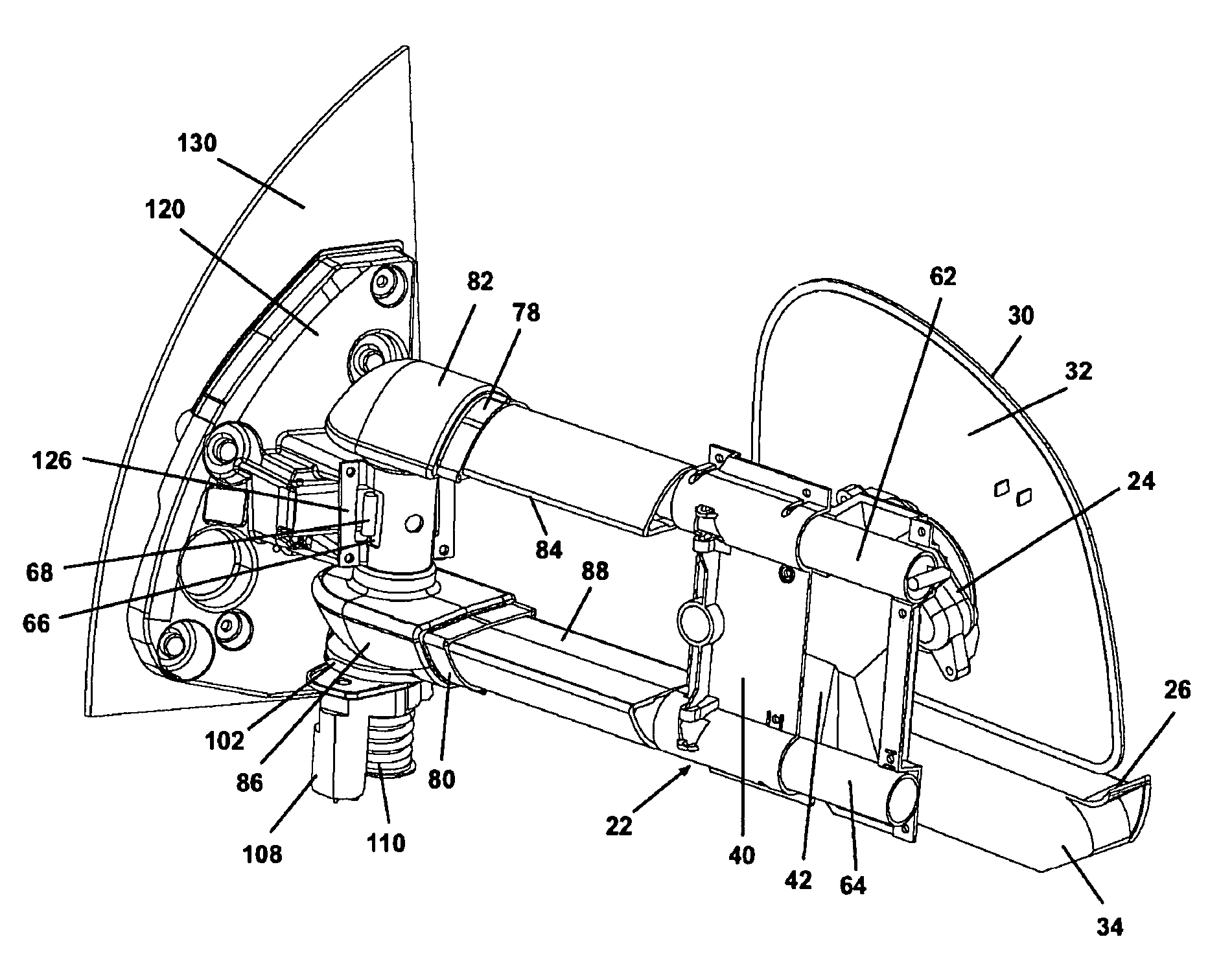
[0068]In the first embodiment, the powerextend actuator 92 is installed on the powerextend adapter 90 to hold the powerextend actuator 92 to the tube assembly 60 so that the actuator drive shaft 222 extends longitudinally through the upper arm sleeve 48. The powerextend nut follower 94 is threaded onto the actuator drive shaft 222 and attached to the shell 20 or the upper shell bracket 42 through a suitable fastener inserted through the aperture 228 into a mounting post 136 or a suitable receptacle in the upper shell bracket 42. The upper linear bearing 74 and the lower linear bearing 76 are fixedly attached either to the shell 20 or the upper shell bracket 42 to slidably receive the upper extender tube 62 and the lower extender tube 64, respectively. As the powerextend actuator 92 is selectively activated to translate the powerextend nut follower 94 along the drive shaft 222, the shell 20 and the upper shell bracket 42 will be translated toward or away from the vehicle as the beari...

second embodiment

[0070]In the second embodiment, the powerextend actuator 92 is not utilized, and the extend functionality is accomplished manually. The lower shell bracket 40 is attached to the upper shell bracket 42 as previously described herein to frictionally engage the tubes 62, 64. The frictional force between the bracket assembly 22 and the tubes 62, 64 can be adjusted by adjusting the spring compression to maintain the shell 20 in a selected extended position during anticipated normal operating conditions while enabling the translation of the shell 20 relative to the tube assembly 60 through the application of sufficient translating force. The pivot actuator assembly 100 will operate to fold and unfold the mirror assembly 10 relative to the vehicle as described above.

[0071]In the third embodiment, the powerextend actuator 92 and the upper shell bracket 42 are assembled and operated as described for the first embodiment. The lower shell bracket 40 is not used, nor is the pivot actuator assem...


PUM


Abstract

An external rearview mirror assembly comprises an arm assembly comprising a pair of parallel support arms rigidly attached to a pivot tube which connects the arm assembly to a base. The pivot tube is held to the base in a cradle which is securely holds the arm assembly to the base while enabling the arm assembly to pivot relative to the base. A motorized powerfold mechanism is used to fold the reflective element assembly against the vehicle, and a motorized powerextend mechanism is used to adjust the position of the reflective element assembly outwardly of the vehicle.

Description

CROSS-REFERENCE TO RELATED APPLICATION[0001]This application claims the benefit of U.S. provisional application Ser. No. 60 / 481,323, filed Sep. 2, 2003, which is incorporated herein in its entirety.FIELD OF THE INVENTION[0002]The invention relates generally to a rearview mirror assembly for a motor vehicle and more particularly to a rearview mirror assembly which can be selectively extended and folded.DESCRIPTION OF THE RELATED ART[0003]Motor vehicles typically include at least one external rearview mirror assembly for providing the operator with a rearward view. The mirror assembly typically includes a base for mounting the assembly to the vehicle, a reflective element assembly for providing the rearward view, and an arm assembly connecting the reflective element assembly to the base. It is well known to configure the arm assembly to enable the reflective element assembly to be selectively extended outwardly of the vehicle to provide an enhanced rearward view, such as when a traile...

Claims


Application Information

Patent Timeline
Patent Type & Authority Patents(United States)
IPC IPC(8): G02B7/182
CPCB60R1/0605B60R1/0607B60R1/078
Inventor BODDY, IANFOOTE, KEITH D.PETERSON, KENNETH C.
Owner MAGNA MIRRORS OF AMERICA INC
Why Eureka
Try Eureka