Arc fault circuit interrupter for a compressor load

a compressor load and circuit interrupter technology, applied in the direction of fault current resposes, emergency protective arrangement details, electrical equipment, etc., can solve the problems of damage or fire, arc fault is an unintentional arcing condition in an electrical circuit, arc faults do not generate currents of either sufficient instantaneous magnitude or sufficient average rms current,

Active Publication Date: 2007-09-11
EATON INTELLIGENT POWER LTD
View PDF17 Cites 51 Cited by
  • Summary
  • Abstract
  • Description
  • Claims
  • Application Information

AI Technical Summary

Problems solved by technology

An arc fault is an unintentional arcing condition in an electrical circuit.
Arc faults can be caused, for instance, by worn insulation between adjacent bared conductors, by exposed ends between broken conductors, by faulty electrical connections, and in other situations where conducting elements are in close proximity.
Because of their intermittent and high impedance nature, arc faults do not generate currents of either sufficient instantaneous magnitude or sufficient average RMS current to trip the conventional circuit interrupter.
Even so, the arcs can cause damage or start a fire if they occur near combustible material.
It is not practical to simply lower the pick-up currents on conventional circuit breakers, as there are many typical loads, which draw similar currents and would, therefore, cause nuisance trips.
Fulfilling this requirement is difficult because normal load currents of capacitor-start motors used in compressors typically exhibit phase and amplitude modulation, as well as harmonic content.
As a result, the challenge is to quickly and reliably identify an arcing current which is superimposed over a much larger, harmonic-laden, amplitude- and phase-modulated compressor current.

Method used


Image

  • Arc fault circuit interrupter for a compressor load
  • Arc fault circuit interrupter for a compressor load
  • Arc fault circuit interrupter for a compressor load

Examples


example 1

[0070]For example, at 320, if the difference 321, Δi_difference, is greater than a first threshold, then an arc is assumed to occur during the current line cycle, and a suitable increment is added to an accumulator (e.g., a trip bucket). This difference 321 deals with the detection of the arc and is based on the difference between the rising edge slope 310 and the falling edge slope 308 of the current. Otherwise, if the test fails, then the accumulator is decremented (e.g., at 410 of FIG. 11C). For example, at 322, if the accumulator exceeds a second threshold, then the trip signal 25 is asserted to trip the circuit breaker 2.

example 2

[0071]One example of the first threshold of Example 1 is a suitable fixed value (e.g., empirical).

example 3

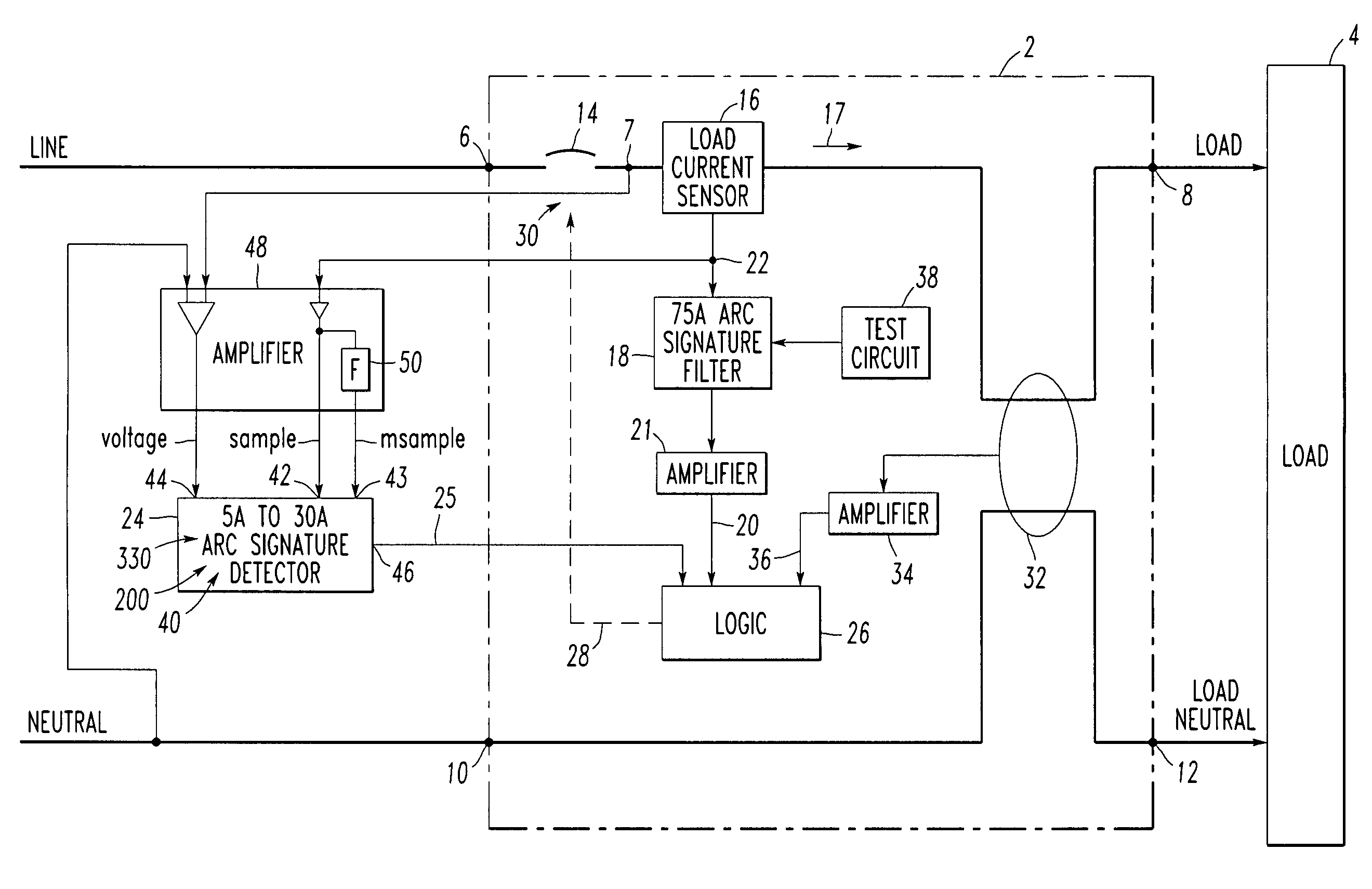
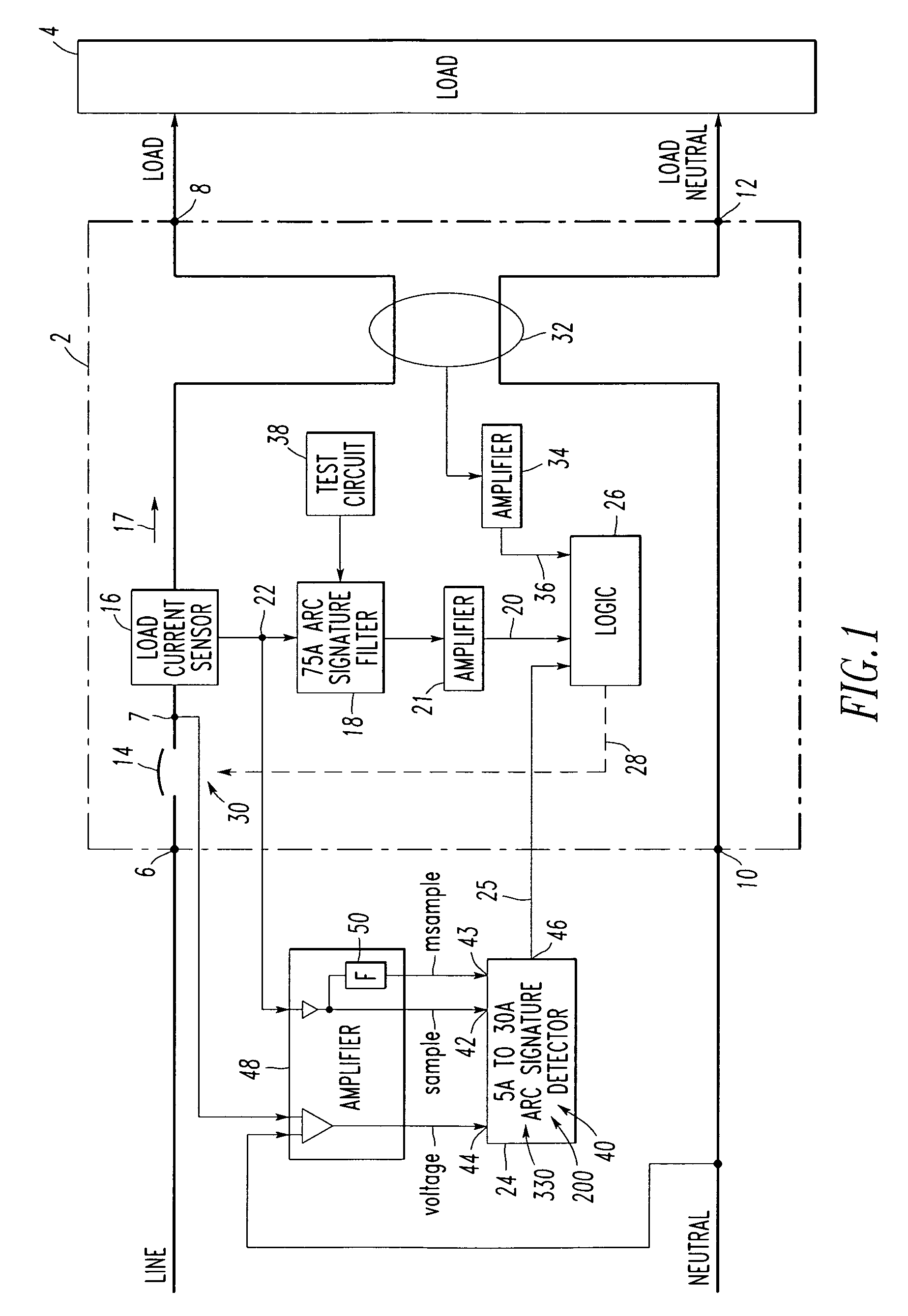
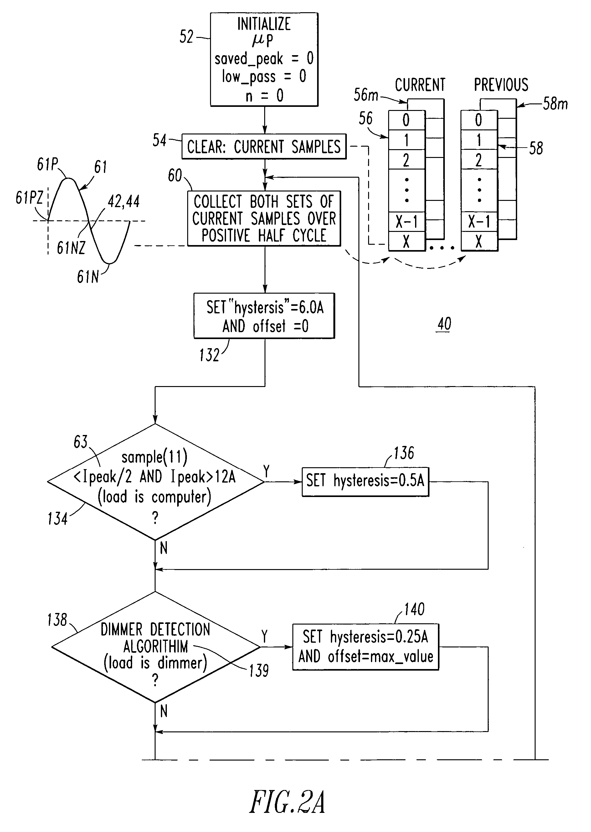
[0072]Another example is a threshold value based on current amplitude. For instance, this value may be proportional to the maximum current amplitude, Ipeak 63 (FIG. 2A), during the corresponding half-cycle. In this case, as the amplitude of the current increases, then a greater difference in the rising edge slope 310 and the falling edge slope 308 is needed to indicate an arc.


PUM


Abstract

An arc fault circuit interrupter includes separable contacts electrically connected between line and load terminals, and a current sensor adapted to sense current flowing between the terminals and through the contacts. An arc fault detection circuit is adapted to collect a plurality of samples of the sensed current for a line cycle, determine a first slope of the sensed current at about a zero crossing of a line voltage, determine a magnitude of one of the samples at about the zero crossing, determine a second slope of the sensed current at another one of the samples having about the magnitude, with the first slope being opposite in polarity with respect to the second slope. The arc fault detection circuit calculates a difference between the slopes, and generates a trip signal as a function of the difference. An operating mechanism is adapted to open the contacts responsive to the trip signal.

Description

CROSS-REFERENCE TO RELATED APPLICATIONS[0001]This application is related to commonly assigned:[0002]U.S. pat. application Ser. No. 10 / 895,158, filed Jul. 20, 2004, entitled “Arc Fault Circuit Interrupter”; and[0003]U.S. pat. application Ser. No. 11 / 100,363, filed Apr. 6, 2005, entitled “Method and Arc Fault Circuit Interrupter Employing a Hysteresis Value for Compressor Rumble”.BACKGROUND OF THE INVENTION[0004]1. Field of the Invention[0005]This invention relates generally to circuit interrupters and, more particularly, to circuit interrupters including an arc fault trip mechanism which responds to sputtering arc faults.[0006]2. Background Information[0007]Arcing is a luminous discharge of electricity across an insulating medium, usually accompanied by the partial volatilization of electrodes. An arc fault is an unintentional arcing condition in an electrical circuit. Arc faults can be caused, for instance, by worn insulation between adjacent bared conductors, by exposed ends betwee...

Claims


Application Information

Patent Timeline
Patent Type & Authority Patents(United States)
IPC IPC(8): H02H3/16
CPCH02H1/0015H02H3/44H02H1/04
Inventor PARKER, KEVIN L.ELMS, ROBERT T.
Owner EATON INTELLIGENT POWER LTD
Why Eureka
Try Eureka