Control apparatus of engine

a control apparatus and engine technology, applied in the direction of electric control, machines/engines, liquid fuel feeders, etc., can solve the problem of difficult to feed back a combustion state at several cycles, and achieve the effect of accurate detection of egr flow rate, high response, and preventing torque fluctuation and deterioration of exhaust gas

Inactive Publication Date: 2007-09-18
HITACHI LTD
View PDF6 Cites 22 Cited by
  • Summary
  • Abstract
  • Description
  • Claims
  • Application Information

AI Technical Summary

Benefits of technology

[0007]The present invention is made by taking the problem mentioned above into consideration, and an object of the present invention is to provide an apparatus properly controlling an ignition combustion, in an engine having a premixed compression ignition combustion mode, particularly at a transient time such as an accelerating time, a decelerating time or the like.
[0027]In accordance with the present invention described above, in the engine having the premixed compression ignition combustion mode, it is possible to accurately detect the EGR flow rate and feed back the EGR flow rate at a high response by arranging the detecting sensor detecting the EGR flow rate in the EGR flow path, particularly at the transient time such as the accelerating time, the decelerating time or the like. Accordingly, it is possible to properly control the ignition combustion in the premixed combustion mode, and it is possible to prevent a torque fluctuation and a deterioration of an exhaust gas (NOx, soot).

Problems solved by technology

Further, an exhaust air sensor such as a linear O2 or the like has a problem in view of a response, and it is hard to feed back a combustion state at several cycles.

Method used


Image

  • Control apparatus of engine
  • Control apparatus of engine
  • Control apparatus of engine

Examples


Embodiment Construction

[0037]A description will be given below of embodiments in accordance with the present invention with reference to the accompanying drawings.

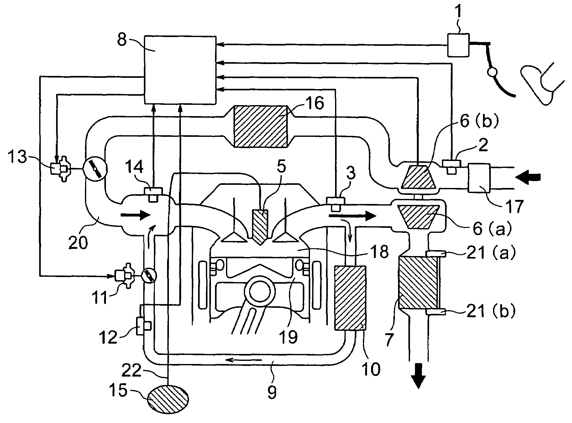
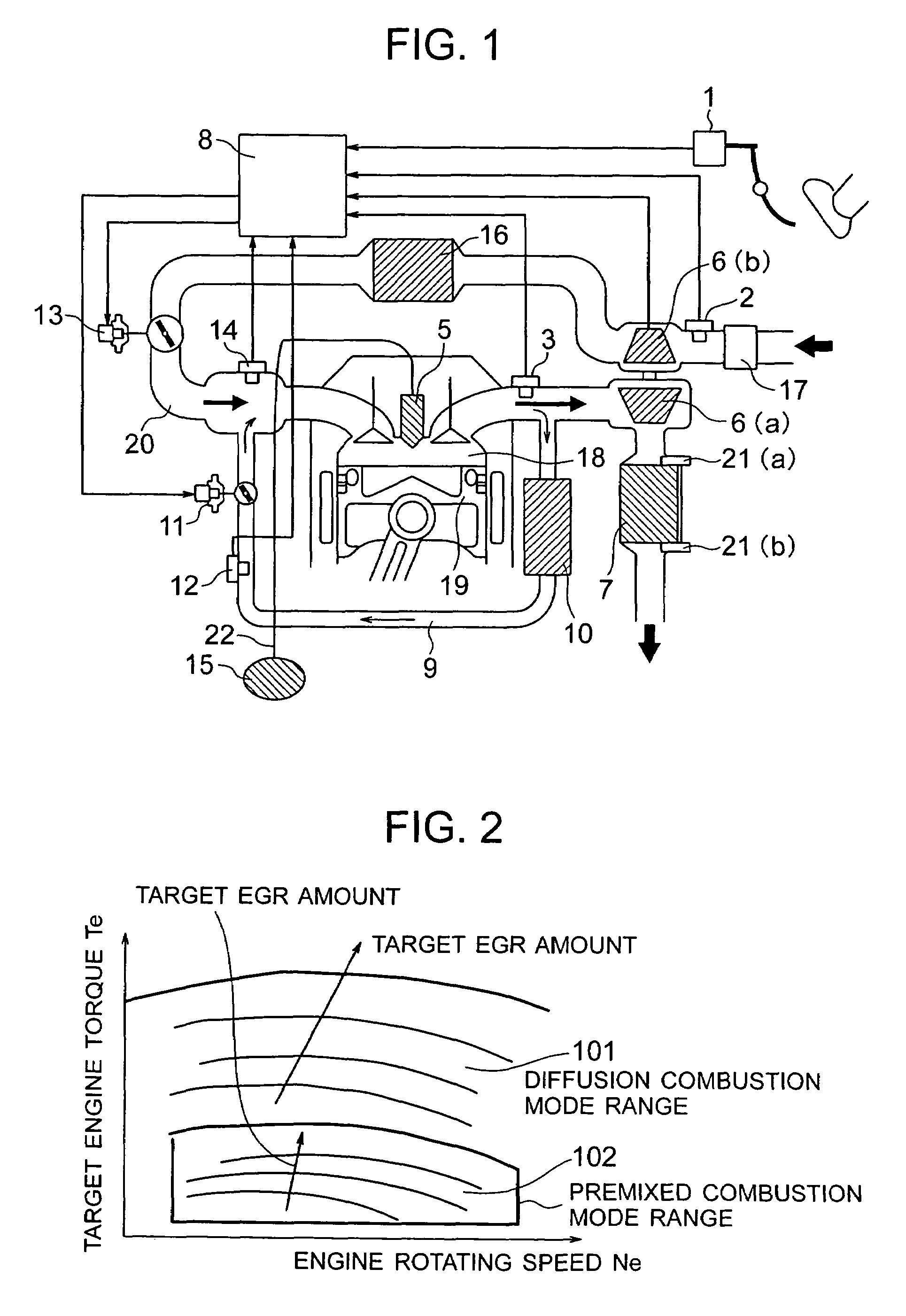
[0038]FIG. 1 shows a structural view of a control apparatus of an engine in accordance with a first embodiment of the present invention. Reference numeral 19 in FIG. 1 denotes an engine. There are arranged an air cleaner 17, an air flow sensor 2, a compressor 6(b) of a supercharger, an intercooler 16, a throttle 13 adjusting an intake air amount, an intake port 20, and a fuel injection valve (hereinafter, refer to as an injector) 5, from an upstream side of the engine 19. An intake air amount control means in the present embodiment is constituted by the compressor 6(b) of the supercharger, the intercooler 16 and the throttle 13, and the intake air amount detecting means is constituted by the air flow sensor 2. The injector 5 is formed as a type of directly injecting a fuel to the combustion chamber 18. It is preferable that the throttle 13 is co...


PUM


Abstract

In an engine having a premixed combustion mode, an EGR flow rate estimating precision is deteriorated at a transient time, and a torque fluctuation and an exhaust gas deterioration are caused. In an engine control apparatus having a premixed combustion mode and a diffusion combustion mode, a sensor detecting an EGR flow rate is arranged in an EGR flow path of the engine, and a cylinder state of the engine is estimated by using an output value of the sensor detecting the EGR flow rate at a time when the engine is in the premixed combustion mode. Since it is possible to accurately detect the EGR flow rate at the transient time and feed back the EGR flow rate at a high response, it is possible to prevent a torque fluctuation and an exhaust gas deterioration.

Description

BACKGROUND OF THE INVENTION[0001](1) Field of the Invention[0002]The present invention relates to a technique preferably executing a combustion control at a time of a premixed combustion mode in a control apparatus of an engine having a premixed combustion mode.[0003](2) Description of Related Art[0004]In a diesel engine, there is considered to employ a premixed combustion mode which burns an air-fuel mixture in a state of premixing the air-fuel mixture as much as possible, and reduces NOx. In order to establish the combustion, a premixed gas is formed by finishing a fuel injection as early as possible in an intake stroke or a compression stroke. On the other hand, in the light of a combustion slapping sound generation due to a sharp ascent of a cylinder internal pressure, ensuring a combustion control robustness or the like, there is considered a method of achieving a premixed combustion mode by introducing a lot of EGR at a time of a low load, and ensuring an ignition lag time on ...

Claims


Application Information

Patent Timeline
Patent Type & Authority Patents(United States)
IPC IPC(8): F02D41/00F02M1/00
CPCF02D41/0072F02D41/107F02D41/3035F02D41/307F02D41/3076F02M25/0754F02D41/0007F02D41/1456F02D41/18F02D41/222F02D2041/0075F02D2200/501F02D2200/602F02D2250/28F02M25/0707Y02T10/47F02M26/05F02M26/47Y02T10/40
Inventor YAMAOKA, SHIROSUKEGAWA, YOSHIHIROTOKUYASU, NOBORUIGARASHI, SHINYAFUKATSU, KATSUAKIKADOHIRO, TAKASHIIWAKI, HIDEFUMIICHIHARA, TAKANOBU
Owner HITACHI LTD
Why Eureka
Try Eureka