
Steerable soil displacement hammer

a technology of soil displacement and hammer, which is applied in the direction of directional drilling, artificial islands, foundation engineering, etc., can solve the problems of tumbling bore movement of appliances, damage to underground pipelines or fittings, and considerable design and mechanical complexity, and achieve the effect of easy steering

Inactive Publication Date: 2007-09-18
TRACTO TECHN
View PDF18 Cites 12 Cited by
  • Summary
  • Abstract
  • Description
  • Claims
  • Application Information

AI Technical Summary

Benefits of technology

[0023]The invention is now based on the object of providing a method which allows an underground boring apparatus to be moved straight ahead and to be steered easily. The invention is also based on the object of providing an underground boring apparatus which is suitable for this method.
[0029]In one particularly preferred embodiment, the holding means are in the form of an oversized forward drive head. This has the advantage that the forward drive head can be rotated, since only the greater frictional resistance of the holding means in the ground may be overcome, although the holding means also ensure isolated rotation of the body, since a smaller friction resistance may be overcome for rotation of the boring apparatus body than for rotation of the forward drive head. In this case, the holding effect of the holding means can be increased as required by the choice of its shape, or can be reduced down to the relatively low but adequate holding force provided by an oversized head with a smooth outer surface.
[0030]In order also to avoid the pivoting resistance in the bore face, the underground boring apparatus according to the invention may have a device for reverse operation, and may be moved away from the bore face for steering. The front area of the forward drive head is then no longer surrounded by compressed earth, but lies freely in the channel in the earth with a full cross section, so that friction forces occur only in the rear area of the forward drive head during pivoting, and lateral movement of the earth during pivoting of the forward drive head is considerably reduced, and preferably avoided.
[0031]It is particularly advantageous to use the technique of moving the underground boring apparatus in reverse in conjunction with an oversize head, in order to carry out the steering process. The oversize forward drive head not only ensures that the body of the underground boring apparatus, which has a smaller diameter, can be rotated easily with the aid of the longitudinal element, (for example the supply line) while in the process ensuring that the head is held adequately in the ground, but also that the head finds an adequate pivoting space when pivoting, when the underground boring apparatus and hence the forward drive head have been moved backward, in order to remove the forward drive head from the bore face. However, the oversize section can also be provided separately from the forward drive head and can then be connected to the forward drive head via a coupling element.
[0032]In this case, it is advantageous for the forward drive head not to have any elements which cause displacement of the surrounding earth during pivoting once the underground boring apparatus has been moved back. In one embodiment of the invention, the oversize section can also be provided on an element, for example a ring, which does not change its axial position during pivoting of the forward drive head, so that there is no need to overcome any friction resistance of the earth during pivoting, either.
[0033]During pivoting of the head, the underground boring apparatus can be moved forward and backward two or more times, in order to further ease the steering process.

Problems solved by technology

Secondly, uncontrolled deviation of the underground boring apparatus from the nominal boring axis can lead to damage to underground pipelines or fittings.
In order to move straight ahead, the underground boring apparatus or the forward-drive head is caused to rotate, which leads to a tumbling boring movement of the appliance, running essentially straight ahead.
Although this apparatus and procedure allow the underground boring apparatus to be controlled to a certain extent, they involve considerable design and mechanical complexity since, in addition to the system for driving the underground boring apparatus forward, a system must be provided for rotation, and a linkage must be provided for transmitting the rotation.
The linkages are relatively rigid, impede the steering process, and cannot be moved from the trench to the surface.
However, extensive equipment must be provided for each borehole for this purpose and, in particular, must be transported (linkage, drive), thus increasing the amount of effort and the costs.
Since the steering head position is unknown outside the borehole, it is also impossible to find out how much hose rotation is required—with or without overcoming the difference angle—to move the steering position to the correct initial position for turning.
However, the problem still remains that the forward drive head is fixed in the highly compressed earth surrounding it.
It is virtually impossible to use the appliance described in PCT WO 94 / 05941 in practice, since the forces required to rotate the underground boring apparatus and the forward drive head are so large that rotation is frequently impossible or leads to kinking of the compressed air hose.
Furthermore, the guide plates on the forward-drive head often result in uncontrolled deflection of the appliance in an undesirable direction, for example due to stones or the like.
However, when moving straight ahead, it is necessary to carry out a continuous to and fro steering movement by using compressed-air through the compressed air hose, which in some circumstances leads to undesirable control effort.

Method used


Image

  • Steerable soil displacement hammer
  • Steerable soil displacement hammer
  • Steerable soil displacement hammer

Examples


Embodiment Construction

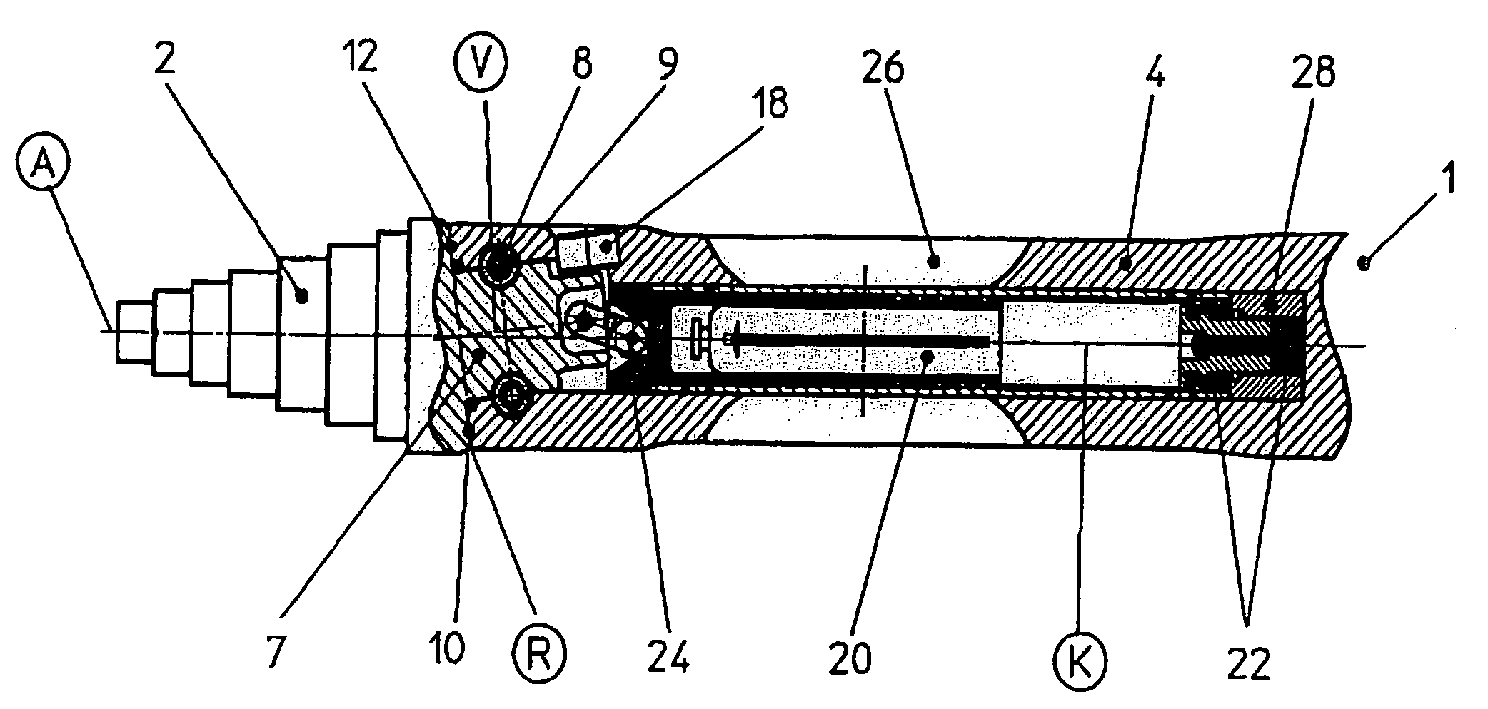
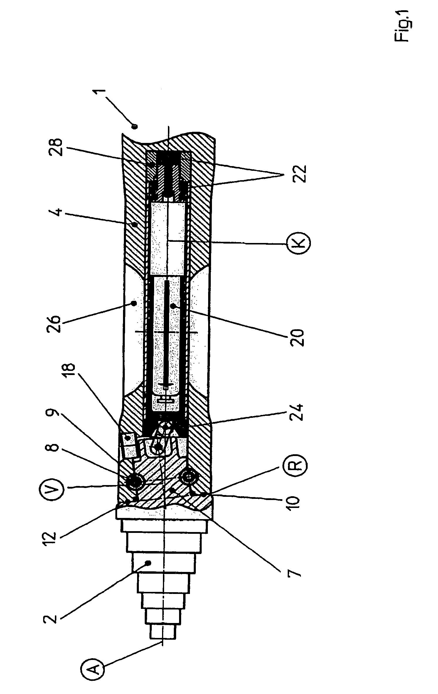
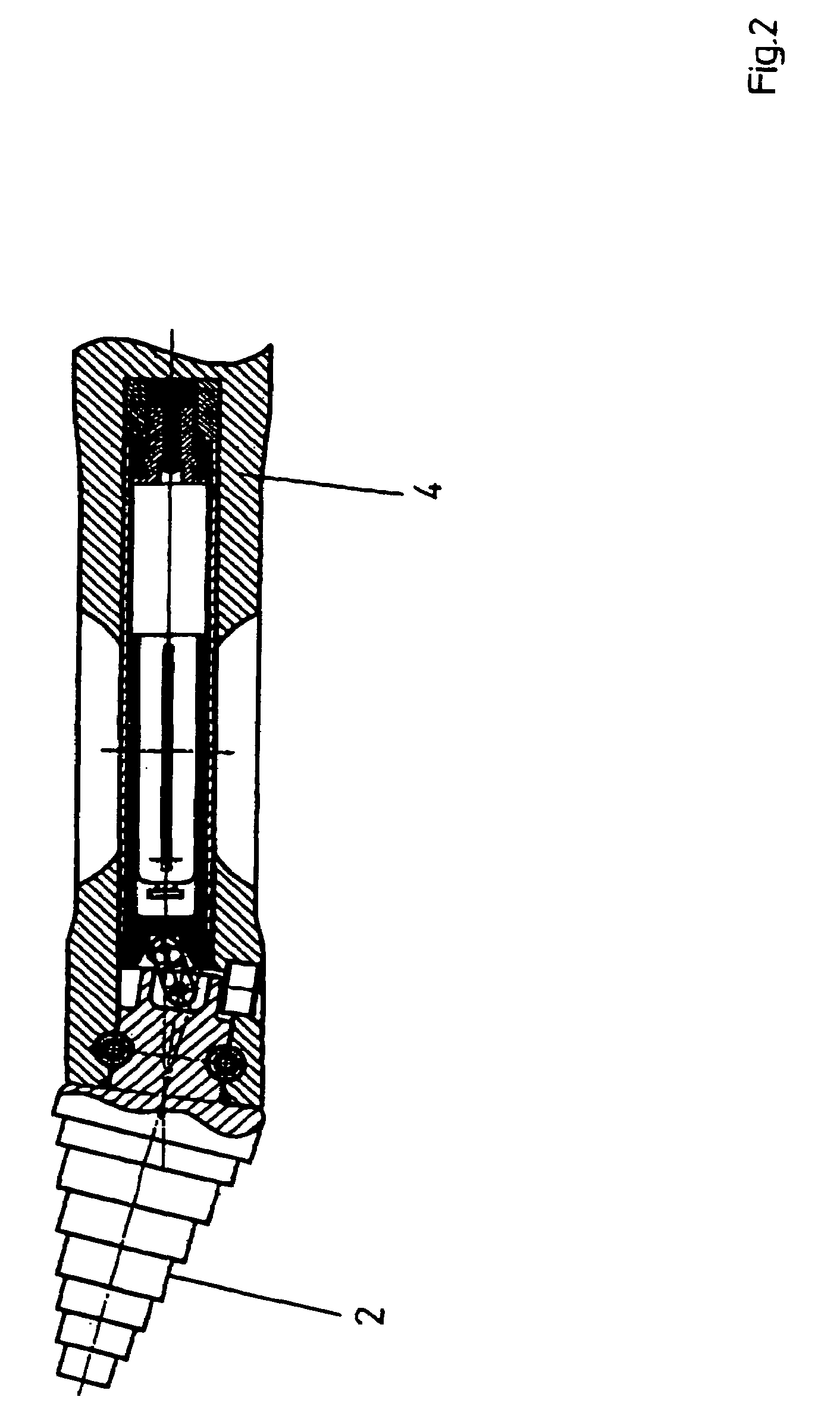
[0042]The underground boring apparatus 1 has a forward drive head 2 and a body 4 with a hammer mechanism. The head 2 has a rotation journal 7 and is mounted in the front end of the body via a rotating bearing 8 with clamping pins 9 such that it can rotate. The rotation journal 7 and the rotating bearing 8 are arranged such that the rotation axis V of the forward drive head 2 is arranged at an angle α with respect to the axis K of the body 4.

[0043]The rotation plane R, which is formed by the rear contact surface 10 of the forward drive head 2 and by the front contact surface 12 of the body 4, lies at right angles to the rotation axis V of the forward drive head. This plane, and hence also the rear contact surface 10 of the forward drive head, is likewise at an angle α with respect to the plane of symmetry or axis A of rotational symmetry of the forward drive head 2, with this angle α corresponding to the angle between the rotation journal axis and the axis of symmetry A. This means t...


PUM


Abstract

The invention relates to a steerable soil displacement hammer for horizontal ground boring, comprising a body that can be rotated by means of a longitudinal element, and a thrust head that is mounted rotationally in relation to the body. A rotation of the body in relation to the thrust head causes the thrust head to pivot out into an asymmetrical constellation or to pivot to a symmetrical constellation. The invention also comprises a retaining feature which provides a hold in the environment and which permits a relative rotation of the body and simultaneous pivoting of the thrust head. The soil displacement hammer can be driven forwards or backwards and the retaining feature is situated in the area of the pivot axis of the thrust head.

Description

CROSS-REFERENCE TO RELATED APPLICATIONS[0001]The invention relates to a steerable underground drilling or boring apparatus for forming horizontal bores in the ground having a forward drive head, which can rotate with respect to the boring apparatus body, and to a method for steering such an underground boring apparatus, and claims priority over German Patent Application 100 52 574.1, to whose contents reference is made.BACKGROUND OF INVENTION[0002]Fundamentally, when boring underground, there is a need to guide the underground boring apparatus to a specific destination, or to move it on a desired track. Particularly when boring horizontally, the directional accuracy of the underground boring apparatus, which in some cases is used in particular underground in densely built-up regions with a complex infrastructure, plays a major role. Firstly, the underground boring apparatus must be able to accurately reach a destination trench, which is frequently tightly constrained, in order to ca...

Claims


Application Information

Patent Timeline
IPC IPC(8): E21B7/04E21B7/06E21B7/08E21B7/26E21B10/36
CPCE21B7/067E21B7/068E21B7/26E21B10/36
Inventor PUTTMANN, FRANZ-JOSEF
Owner TRACTO TECHN
Learn More