
Apparatus for controlling electric power from fuel cell

a technology of electric power and apparatus, which is applied in the field of apparatus for controlling electric power from a fuel cell, can solve the problems of reducing the transient response of the the insufficient output power of the fuel cell, and the inability to meet the needs of the electric power supply, so as to prevent the output voltage of the fuel cell from being produced excessively, and secure the response of the electric power. , the effect of preventing the excess production of electric current of the fuel

Inactive Publication Date: 2007-09-18
NISSAN MOTOR CO LTD
View PDF4 Cites 4 Cited by
  • Summary
  • Abstract
  • Description
  • Claims
  • Application Information

AI Technical Summary

Benefits of technology

[0010]It is an object of the present invention to provide an apparatus for controlling electric power from a fuel cell, which prevents electric current of the fuel cell from being produced excessively and prevents output voltage from the fuel cell from radically decreasing at a transient time. It is another object of the present invention to provide an apparatus for controlling electric power from a fuel cell to secure the response of the electric power.

Problems solved by technology

Accordingly, the output power from the fuel cell may not be sufficiently produced.
However, the transient response of the output power from the fuel cell is reduced.
However, the second conventional art has following problems.
Thus, an initial object, which is to prevent the output voltage from being lowered, cannot be achieved.
However, even if the pressures of the air and hydrogen do not reach sufficient values, the output power is produced due to the mass flow rate of the air.
Therefore, the output voltage from the fuel cell may be radically lowered, so that the output power from the fuel cell may not be sufficiently produced.

Method used


Image

  • Apparatus for controlling electric power from fuel cell
  • Apparatus for controlling electric power from fuel cell
  • Apparatus for controlling electric power from fuel cell

Examples


Embodiment Construction

[0038]Hereafter, in order to describe the present invention more in detail, preferred embodiments of this invention will be explained with reference to the accompanying drawings below.

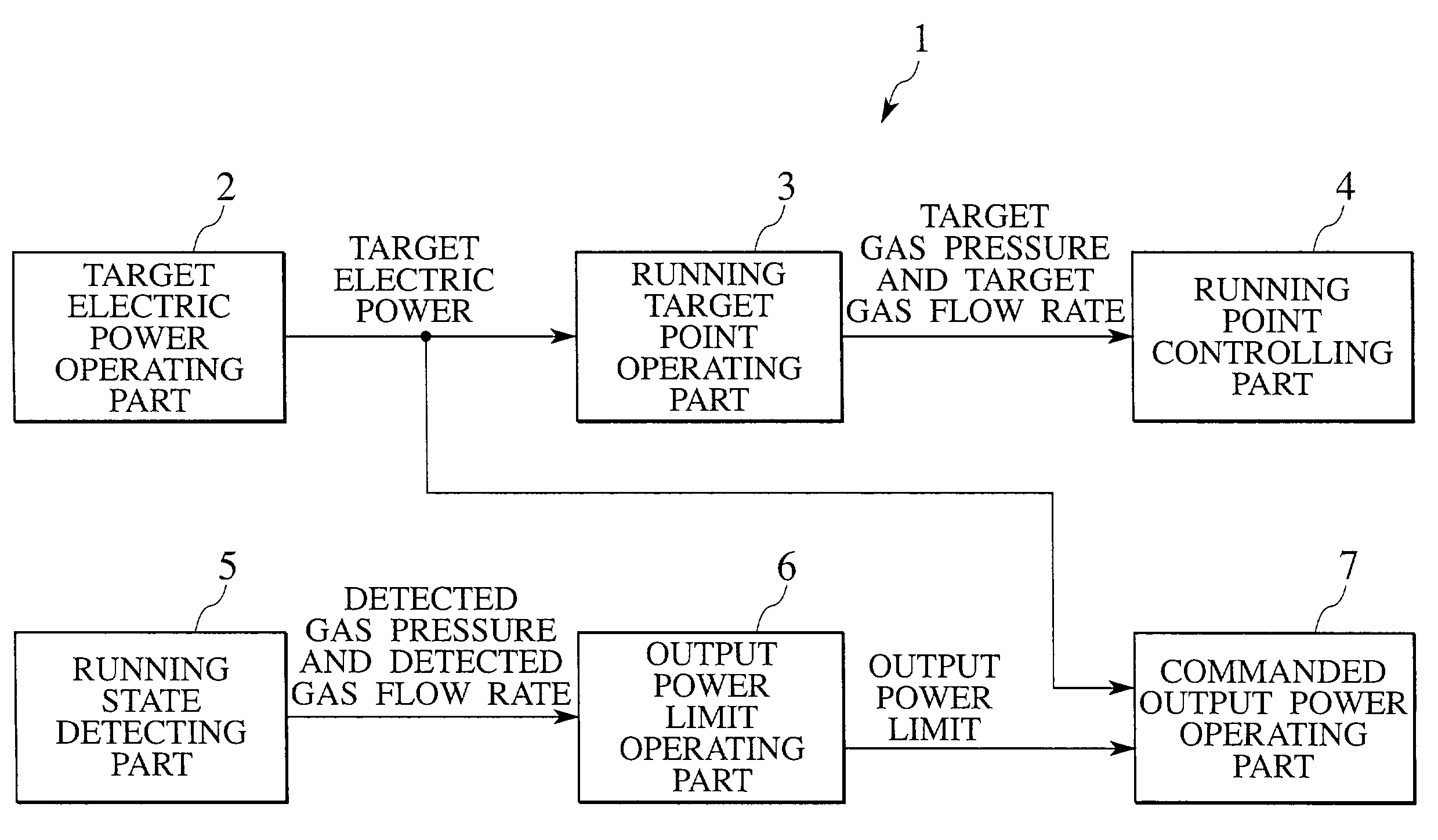
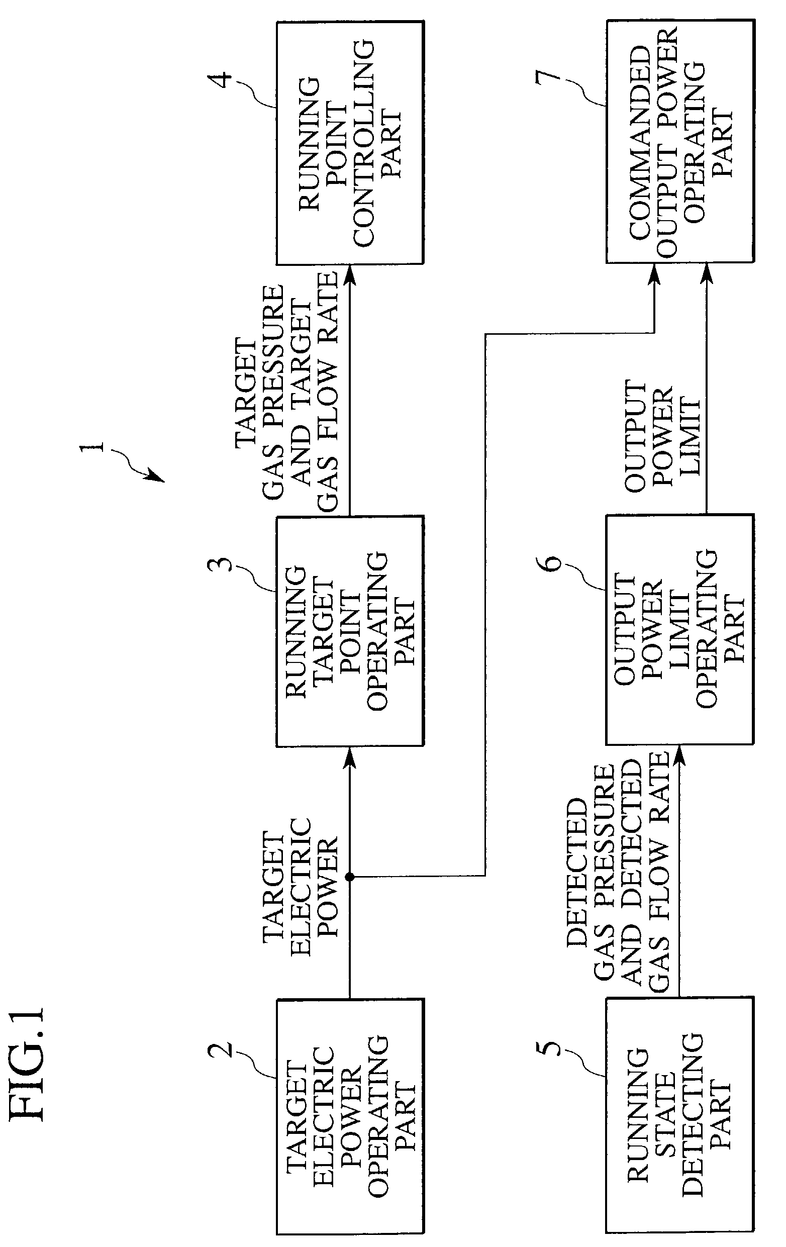
[0039]FIG. 1 shows a substantial structure of an apparatus for controlling electric power of a fuel cell according to the present invention. The apparatus for controlling electric power 1 is constituted by a target electric power operating part 2, a running target point operating part 3, a running point controlling part 4, a running state detecting part 5, an output power limit operating part 6 and a commanded output power operating part 7.

[0040]The target electric power operating part 2 is target electric power operating means for operating target electric power of the fuel cell. The running target point operating part 3 is a running target point operating means for operating running target points of pressure and mass flow rate of gases (air and hydrogen) based on an output from the target electric po...


PUM

PropertyMeasurementUnit
electric poweraaaaaaaaaa
pressureaaaaaaaaaa
mass flow rateaaaaaaaaaa

Abstract

A target electric power operating part (2) operates a target electric power of a fuel cell. A running target point operating part (3) operates targets of both pressure of gas and mass flow rate of gas. A running point controlling part (4) controls a running point of the fuel cell. A running state detecting part (5) detects a running state of the fuel cell. An output power limit operating part (6) operates a limit of the output power produced by the fuel cell, based on the running state e.g., pressure of the gas detected in the running state detecting part (5). A commanded output power operating part (7) operates a commanded output power, the commanded output power being defined as a minimum value between an output from the output power limit operating part (6) and an output from the target electric power operating part (2).

Description

BACKGROUND OF THE INVENTION[0001]1. Field of the Invention[0002]The present invention relates generally to a fuel cell system, and more particularly, to an apparatus for controlling electric power from a fuel cell, which takes a transient response of a gas controlling system of the fuel cell into account.[0003]2. Description of the Related Art[0004]A running state (working fluid is gas in this state) may respond slowly as demanded output power from a fuel cell increases. Therefore, producible output power may not satisfy the demanded output power. When the demanded output power increases, if the demanded output power is attempted to be produced, output voltage from the fuel cell may fall and the fuel cell may deteriorate. Japanese Patent Application Laid-Open No. H10-284102 (Hereafter, this application is called a first conventional art.) and Japanese Patent Application Laid-Open No. H7-75214 (Hereafter, this application is called a second conventional art.) are known as conventiona...

Claims


Application Information

Patent Timeline
Patent Type & Authority Patents(United States)
IPC IPC(8): H01M8/04H01M8/12
CPCH01M8/04089Y02E60/50
Inventor SUZUKI, KEISUKE
Owner NISSAN MOTOR CO LTD
Learn More