
Position-measuring device

a technology of measuring device and measuring strip, which is applied in the direction of converting sensor output optically, instruments, material analysis, etc., can solve the problems of only small elongation effect at the outer surface of the measuring strip, inability to compensate for the projection effect, and inability to achieve the effect of simple design

Active Publication Date: 2007-09-18
DR JOHANNES HEIDENHAIN GMBH
View PDF14 Cites 0 Cited by
  • Summary
  • Abstract
  • Description
  • Claims
  • Application Information

AI Technical Summary

Benefits of technology

The present invention relates to a position-measuring device that can be used in a simple design and can combine a measuring strip with a scanning plate. The device has a detector with a planar, two-dimensional, radiation-sensitive surface. The invention allows for a coordinated interaction between the material measure (measuring strip) and the scanning plate, which results in a smaller stripe pattern than the period of the scanning plate. This compensates for the projection effect and allows for a larger detector. The invention also allows for the use of a structured detector and the modification of the period of the measuring gradation and scanning plate to further enhance the detection of the stripe pattern.

Problems solved by technology

Compared with a linear arrangement of the measuring strip (so that it extends in the manner of a scale along a straight line), when working with the ring-like arrangement of the measuring strip, e.g., along a circular arc, effects occur which impair the intensity of the radiation received at the detector of the scanning unit.
For very thin measuring strips having a thickness of markedly less than 300 μm, e.g., less than 100 μm, however, the elongation effect at the outer surface of the measuring strip is only so small that it is no longer able to sufficiently compensate for the projection effect in the case of strong curvatures.
Because of the poor contrast of the intensity pattern, the signal amplitude detected by the detector can become so small that a reliable evaluation for determining position is not possible.
The reverse case is possible, but may be of lesser practical relevance.

Method used


Image

  • Position-measuring device
  • Position-measuring device
  • Position-measuring device

Examples


Embodiment Construction

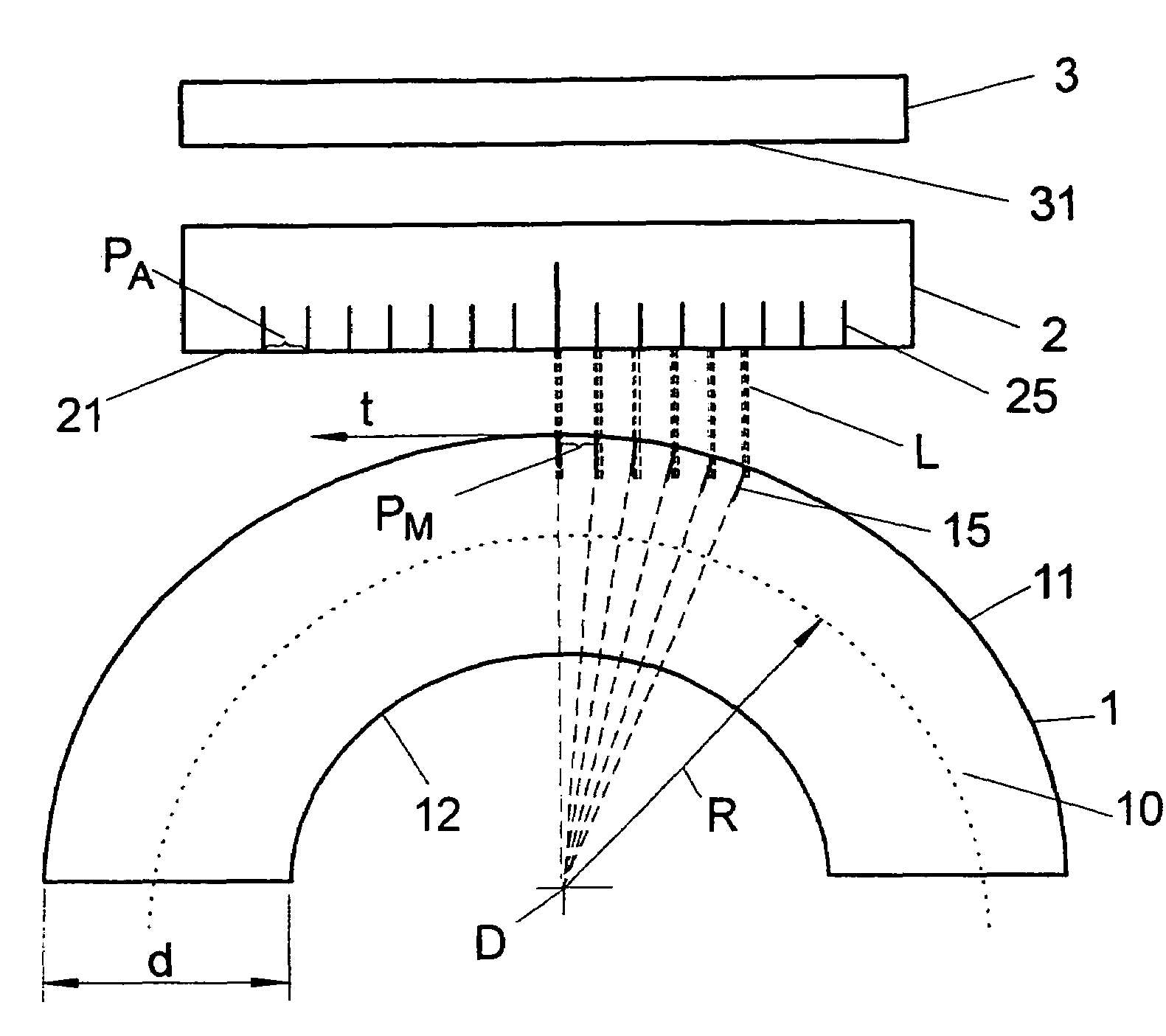
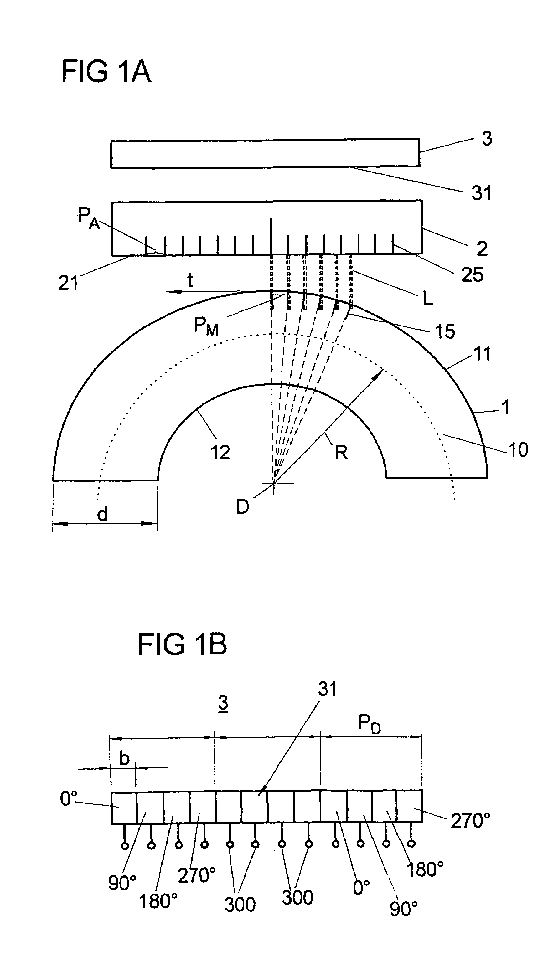
[0049]FIG. 1a illustrates schematically a position-measuring device for angular measurement having a measuring strip 1 of finite thickness d arranged in the shape of a ring along a circular arc, and having a scanning unit which includes a scanning plate 2 and a detector 3 in the form of a photodetector.

[0050]Measuring strip 1 and scanning unit 2, 3 are movable relative to each other, e.g., in that measuring strip 1 is affixed to the outer periphery of a drum rotatable about an axis D, and scanning unit 2, 3 is arranged in a stationary manner in front of outer surface 11 (outer ring surface) of measuring strip 1, (and set apart from it in radial direction R).

[0051]Measuring strip 1 of thickness d, arranged in the shape of a ring along a circular arc 10 having radius R, has an outer ring surface 11 provided with a periodic measuring graduation 15 in the form of a line graduation, as well as an inner surface 12 (inner ring surface). Due to the annular arrangement of flexible measuring ...


PUM

PropertyMeasurementUnit
thicknessaaaaaaaaaa
thicknessaaaaaaaaaa
thicknessaaaaaaaaaa

Abstract

A position-measuring device includes: a measuring graduation provided on a material measure going around in ring-like fashion; a scanning unit for optically scanning the measuring graduation using electromagnetic radiation; a scanning plate with a periodic scanning graduation which is arranged in the beam path of the electromagnetic radiation used for scanning the measuring graduation, so that the radiation interacts both with the scanning graduation and with the measuring graduation; and a detector of the scanning unit, the detector surface of which is used for detecting the electromagnetic radiation after interaction with the scanning graduation and the measuring graduation and which is arranged with a period (PD) for detecting electromagnetic radiation in the form of a stripe pattern. The period PM of the measuring graduation and the period PA of the scanning graduation may be coordinated so that 1 / (1 / PA−1 / PM)<PD.

Description

CROSS-REFERENCE TO RELATED APPLICATIONS[0001]The present application claims priority to Application No. 103 45 018.1, filed in the Federal Republic of Germany on Sep. 23, 2003, and claims priority to Application No. 10 2004 024 581.9,filed in the Federal Republic of Germany on May 12, 2004, each of which is expressly incorporated herein in its entirety by reference thereto.FIELD OF THE INVENTION[0002]The present invention relates to a position-measuring device.BACKGROUND INFORMATION[0003]A position-measuring device for determining the relative position of two objects movable relative to each other along a measuring direction (angular position measuring device) includes: a periodic measuring graduation configured on a ring-like material measure (i.e., on a ring-like support), e.g., in the form of a measuring strip; a scanning unit for optically scanning the measuring graduation using electromagnetic radiation (using light) which is generated in an illumination device (light source) o...

Claims


Application Information

Patent Timeline
Patent Type & Authority Patents(United States)
IPC IPC(8): G01B11/14G01B11/02G01D5/34G01D5/36G01N21/86G01V8/00G01D5/26G01D5/347G01D5/38
CPCG01D5/26G01D5/34707G01D5/38
Inventor TONDORF, SEBASTIANHUBER
Owner DR JOHANNES HEIDENHAIN GMBH
Learn More