Optical head apparatus

a head apparatus and optical technology, applied in the direction of heads, instruments, data recording, etc., can solve the problem that small spots cannot be formed on optical recording media, and achieve the effect of suppressing astigmatism

Inactive Publication Date: 2007-09-18
VOXPATH RS LLC +1
View PDF5 Cites 0 Cited by
  • Summary
  • Abstract
  • Description
  • Claims
  • Application Information

AI Technical Summary

Benefits of technology

[0010]In consideration of the problems listed above, the primary object of this invention is to provide optical head apparatus that enables control of scatter that occurs along the length of the optical path when a laser beam is transmitted through the prism where the No. 1 prism structural member and the No. 2 prism structural member are joined through a partially reflecting face.
[0014]By constructing in this fashion, no matter at what location the laser beam passes through the prism, the difference in optical path length (Δn·d) at each location is not greater than 5 times the wavelength. Thus it is possible to suppress astigmatism due to the prism.
[0017]By constructing the optical head in this fashion, the difference in optical path length (Δn·d) at each location along the path is small, thus it is possible to suppress astigmatism due to the prism.

Problems solved by technology

Consequently, unless there is sufficient control of astigmatism, small spots cannot be formed on optical recording medium 20.

Method used


Image

  • Optical head apparatus
  • Optical head apparatus
  • Optical head apparatus

Examples


Embodiment Construction

[0023]Below, one example of optical head apparatus of this invention is explained with the figures as reference.

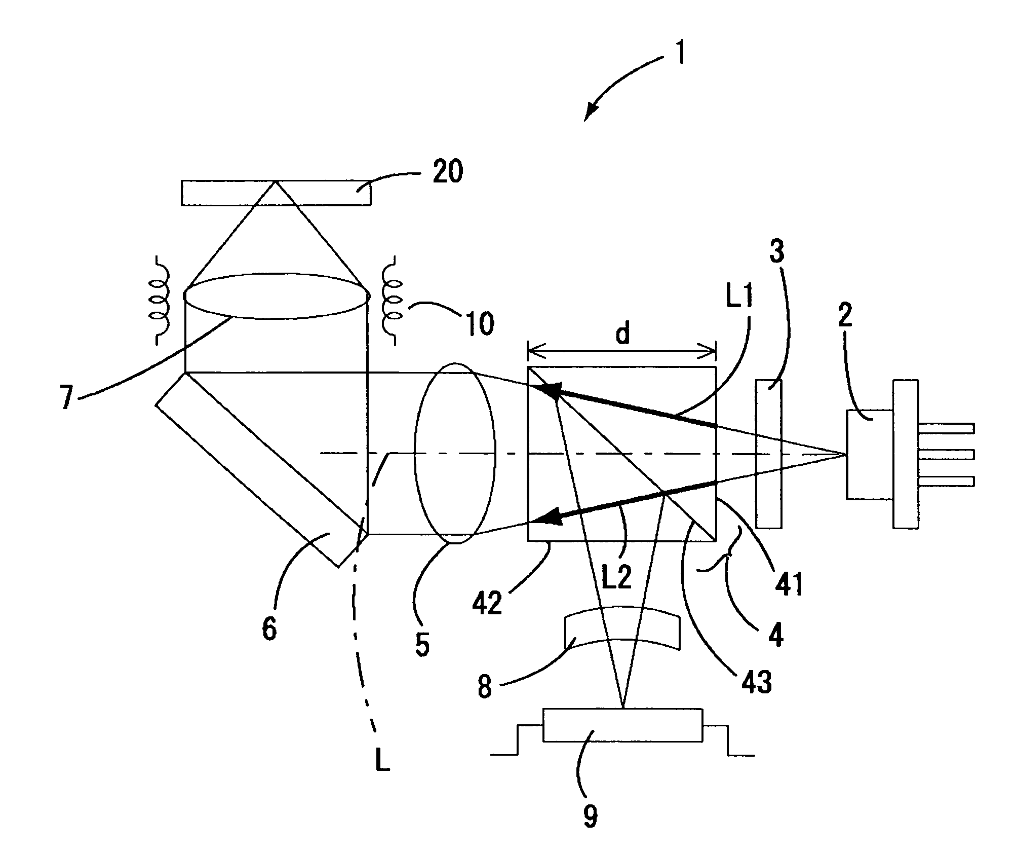
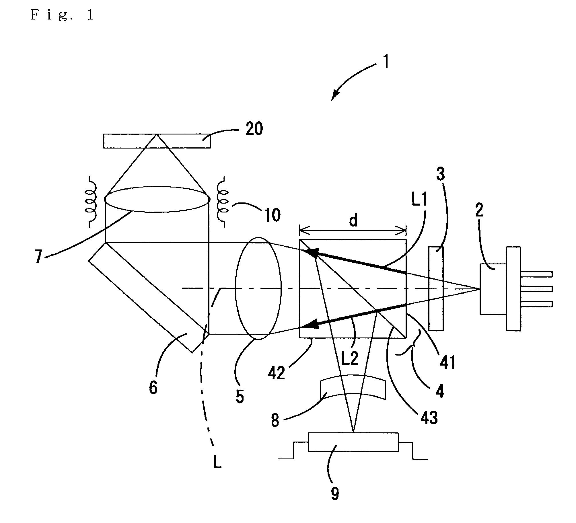
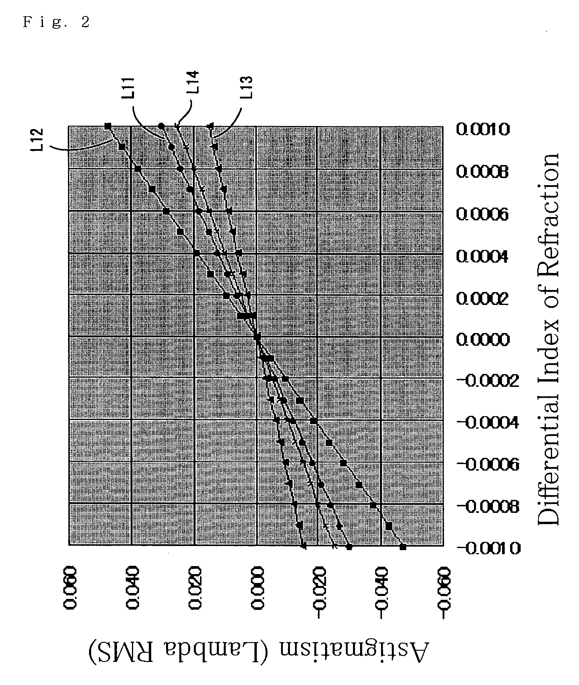
[0024]FIG. 1 is a simplified structural diagram showing optical system in the center of optical head apparatus of this example. FIG. 2 is a graph showing the relationship in optical head apparatus between the size and numeral aperture of the prism and astigmatism due to the prism.

[0025]As shown in FIG. 1, optical head apparatus 1 is a device that performs information recording, information regeneration on optical recording medium such as DVD; laser beam-emitting element 2 comprising a laser diode emitting laser beam of wavelength 650 nm bandwidth, grating 3 for splitting laser beam emitted from this laser beam-emitting element 2 into 3 beams, prism 4 used for optical path synthesis or optical path separation of laser beam emitted from laser beam-emitting element, entering through grating 3, collimating lens 5 to convert laser beam transmitted through prism 4 to parallel li...


PUM

PropertyMeasurementUnit
lengthaaaaaaaaaa
refractive indexaaaaaaaaaa
angleaaaaaaaaaa

Abstract

The present invention is for providing optical head apparatus that can control scatter occurring at locations along the length of the optical path, when laser beam is transmitted through prism constituting the No. 1 prism structural member and the No. 2 prism structural member joined through partially reflecting face. Optical head apparatus 1 performs information recording, information regeneration on an optical recording medium, e.g. DVD; laser beam emitted from laser beam-emitting element is transmitted through a prism. The prism has the structure wherein triangular the No. 1 prism structural member and similarly a triangular No. 2 prism structural member are joined through partially reflecting face.

Description

CROSS-REFERENCE TO RELATED APPLICATIONS[0001]This application claims priority of Japanese Application No. 2003-150278, filed May 28, 2003, the complete disclosure of which is hereby incorporated by reference.BACKGROUND OF THE INVENTION[0002]a) Field of the Invention[0003]This invention relates to optical head apparatus used in recording, regeneration for optical recording medium such as DVD (digital versatile disk).[0004]b) Description of the Related Art[0005]In optical head apparatus used in recording, regeneration for optical recording disk such as CD (compact disk) and DVD, in general, a laser beam-emitting element, a prism for the incident laser beam emitted from this laser beam-emitting element, a collimating lens to convert laser beam transmitted through this prism to parallel light flux, and an objective lens to condense parallel light flux emitted from collimating lens on optical recording medium, are located on an optical path in this order.[0006]Here, the prism is used as ...

Claims


Application Information

Patent Timeline
Patent Type & Authority Patents(United States)
IPC IPC(8): G11B7/135G11B7/00G11B7/08G11B7/12G11B7/1356G11B7/1362G11B7/1374G11B7/1376G11B7/1381G11B7/1392
CPCG11B7/1356G11B7/1362G11B7/1374G11B7/1376G11B7/1381G11B7/13922
Inventor SAKAI, HIROSHI
Owner VOXPATH RS LLC
Why Eureka
Try Eureka