
Optical system for optical disc drive

an optical disc drive and optical disc technology, applied in the field can solve the problems of off-axis aberration and astigmatism of optical disc drives, and achieve the effect of suppressing off-axis aberration and high recording density

Inactive Publication Date: 2007-10-18
ASAHI KOGAKU KOGYO KK
View PDF11 Cites 2 Cited by
  • Summary
  • Abstract
  • Description
  • Claims
  • Application Information

AI Technical Summary

Benefits of technology

[0006]The present invention is advantageous in that it provides an optical system capable of suitably suppressing off-axis aberration such as astigmatism caused in an optical disc drive when recordation or reproduction for an optical disc having a high recording density is performed.
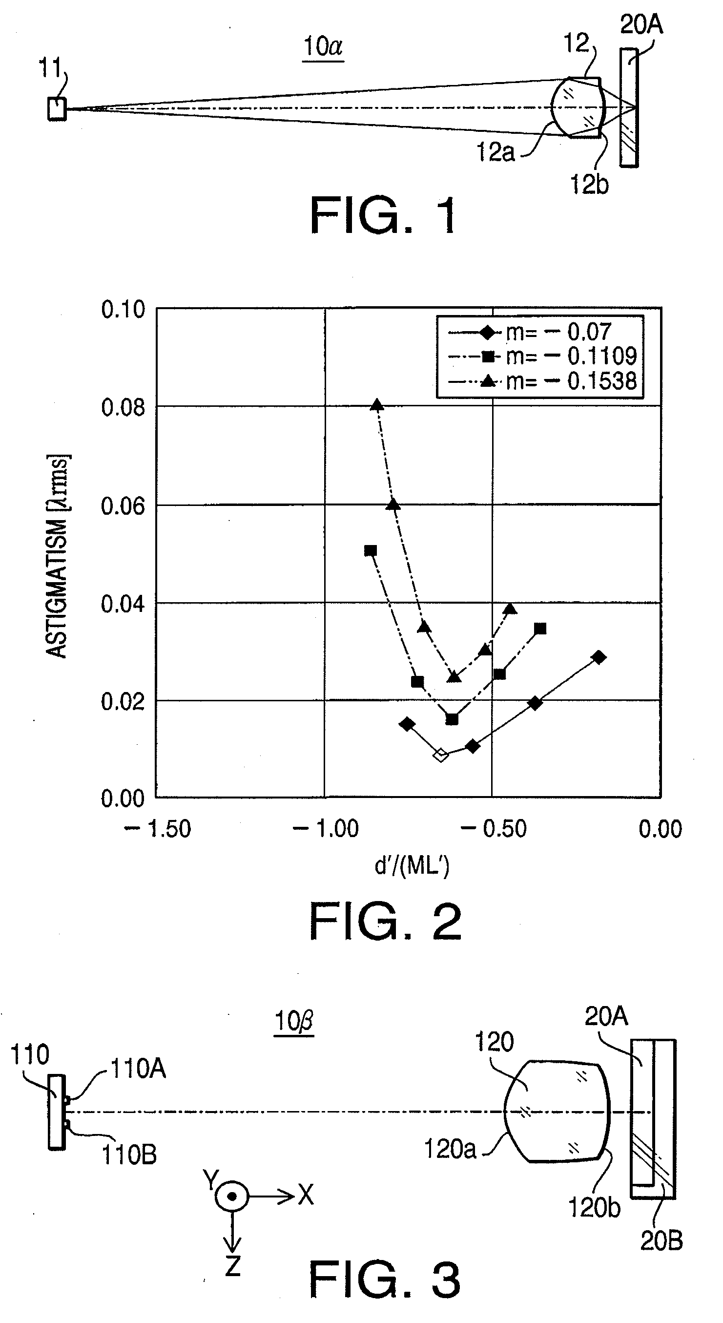
[0009]By thus determining the center thickness of the objective lens to satisfy the condition (1), it is possible to suitably suppress astigmatism caused when the objective lens is moved for a tracking operation.
[0012]By thus determining the center thickness of the objective lens to satisfy the condition (1), it is possible to suitably suppress astigmatism caused when the objective lens is moved for a tracking operation. Astigmatism needs to be suitably corrected particularly for the optical disc which has a relatively thin cover layer and a relatively high recording density. Therefore, by thus configuring the optical disc drive supporting the plurality of types of optical discs to satisfy the condition (1) at least for the optical disc having the relatively thin cover layer, it is possible to suitably suppress aberration while achieving downsizing of the optical system.
[0016]By thus determining the center thickness of the objective lens to satisfy the condition (1), it is possible to suitably suppress astigmatism caused when the objective lens is moved for a tracking operation.
[0019]By thus determining the center thickness of the objective lens to satisfy the condition (1), it is possible to suitably suppress astigmatism caused when the objective lens is moved for a tracking operation. Astigmatism needs to be suitably corrected particularly for the optical disc which has a relatively thin cover layer and a relatively high recording density. Therefore, by thus configuring the optical disc drive supporting the plurality of types of optical discs to satisfy the condition (1) at least for the optical disc having the relatively thin cover layer, it is possible to suitably suppress aberration while achieving downsizing of the optical system.

Problems solved by technology

Although an optical system not having a coupling lens is able to reduce the cost and size thereof, such an optical system has a drawback that when an objective lens is shifted in a direction perpendicular to an optical axis of the objective lens for tracking, the optical system produces off-axis aberration, notably astigmatism, in comparison with an infinite optical system employing a coupling lens.

Method used


Image

  • Optical system for optical disc drive
  • Optical system for optical disc drive
  • Optical system for optical disc drive

Examples


first embodiment

[0038]FIG. 1 is a block diagram of an optical system 10α according to a first embodiment. In FIG. 1, an optical disc 20A having a relatively high recording density and having a relatively thin cover layer (e.g., a DVD) is also illustrated. The optical system 10α includes a light source 11 and an objective lens 12. The optical system 10α is mounted on an optical disc drive capable of recording data to and / or reproducing data from the optical disc 20A which is placed on a turn table (not shown) of the optical disc drive.

[0039]As shown in FIG. 1, the optical system 10α is a finite system not having a coupling lens. In other words, a laser beam emitted by the light source 11 is incident on the objective lens 12 without passing through a coupling lens. In the optical system 10α, a laser beam emitted by the light source 11 is a diverging beam, and the diverging beam is converged only by the objective lens 12. The light source 11 emits the laser beam having a relatively short wavelength so...

second embodiment

[0046]FIG. 3 is a block diagram of an optical system 10β according to a second embodiment. In FIG. 3, an optical disc 20A having a relatively high recording density (e.g., a DVD) and an optical disc 20B having a relatively low recording density are illustrated. The optical disc 20B is, for example, a CD having a cover layer thickness larger than that of the optical disc 20A. The optical system 10 includes a light source 110 and an objective lens 120. The optical disc 10β is mounted on an optical disc drive capable of recording data to and / or reproducing data from a plurality of types of optical discs (i.e., the optical discs 20A and 20B). The optical disc is placed on a turn table (not shown) of the optical disc drive.

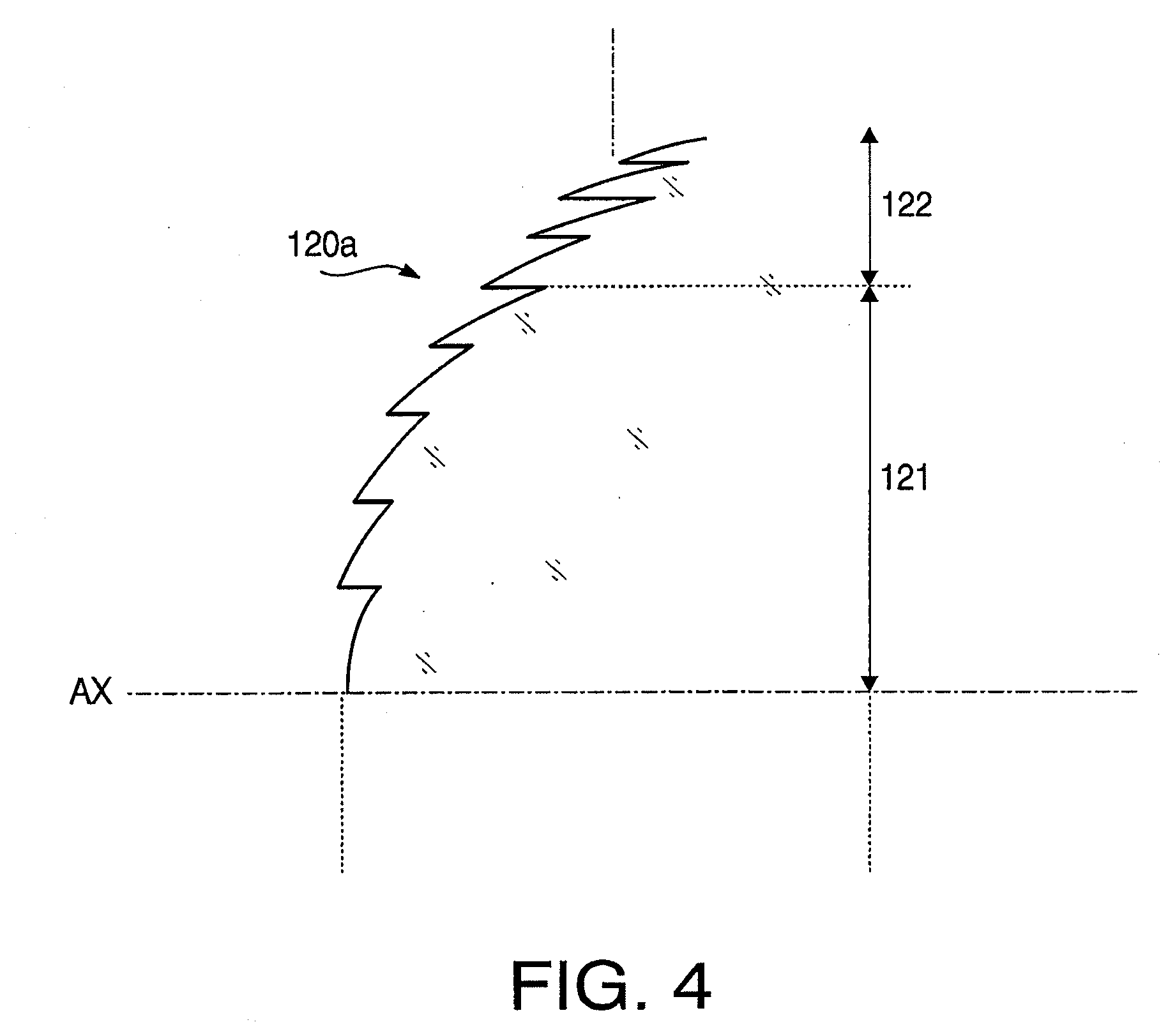
[0047]The light source 110 has two light emitting portions 110A and 110B arranged along a line (i.e., Z-axis direction) which is perpendicular to a X-axis direction, in which the objective lens 120 is allowed to move perpendicularly to a recording surface of the optica...

first example

[0058]Since a first example is a concrete example of the optical system 10α according to the first embodiment, a configuration of the first example is explained with reference to FIG. 1. Specifications of the optical system 10α according to the first example are shown in Table 1.

TABLE 1Optical Disc 20AM−0.1005Design wavelength (nm)655NA0.60L′ (mm)19.5308

[0059]In Table 1 (and in the following similar Tables), the design wavelength is a wavelength suitable for the recording / reproducing operation of the optical disc, M represents magnification of the optical system 10α, NA represents the numerical aperture, and L′ represents the object-to-image distance corresponding to air. Table 2 shows a numerical configuration of the optical system 10α.

TABLE 2SurfacenNumberrd(405 nm)comments#017.4090light source#11.19701.85001.54063objective lens#2−1.60300.5412#3∞0.60001.57995optical disc#4—

[0060]In Table 2 (and in the following similar Tables), “r” represents a radius of curvature (unit: mm) of ea...


PUM


Abstract

There is provided an optical system for an optical disc drive. The optical system is provided with a light source that emits a light beam, and an objective lens to which the light beam emitted by the light source enters. In this configuration, the light beam emitted by the light source is incident on the objective lens without passing through a coupling lens. Further, the optical system satisfies a condition:−0.70≦d′ / (ML′)≦−0.57   (1)where d′ (mm) represents a center thickness of the objective lens corresponding to air, M represents magnification of the optical system, and L′ (mm) represents an object-to-image distance corresponding to air.

Description

BACKGROUND OF THE INVENTION[0001]The present invention relates to an optical system used for an optical disc drive for recording data to and / or reproducing data from an optical disc having a high recording density.[0002]Optical systems for an optical disc drive configured to have a light source, a coupling lens and an objective lens have been widely used. The term “coupling lens” means a lens serving to convert a light beam emitted by the light source into a collimated beam or a lens having a function of changing the degree of divergence of a beam (i.e., changing magnification of the optical system). The coupling lens is used to suppress aberration caused on a recording surface of the optical disc, or to enhance efficiency of used of light in the optical disc drive. Recently, optical systems are required to decrease the number of optical components to achieve cost reduction and downsizing. In each of Japanese Patent Provisional Publications Nos. SHO 61-56314 and HEI 8-334686, a fini...

Claims


Application Information

Patent Timeline
IPC IPC(8): G11B7/00
CPCG11B7/13922G11B7/1374
Inventor KOIZUMI, TOMOKAZUTAKEUCHI, SHUICHI
Owner ASAHI KOGAKU KOGYO KK
Learn More