Polarizing beam splitter, projection optical sysem, projection display

a polarizing beam and projection optical system technology, applied in the field of optical prisms, can solve the problems of difficult to increase brightness, provide poor polarization separation characteristic, and not provide a projected image with a high contrast ratio, so as to suppress the occurrence of astigmatism, improve the focusing performance of the projection optical device or the projection display, and suppress the effect of astigmatism

Inactive Publication Date: 2009-02-19
SONY CORP
View PDF9 Cites 23 Cited by
  • Summary
  • Abstract
  • Description
  • Claims
  • Application Information

AI Technical Summary

Benefits of technology

[0043]According to the embodiments of the invention, since the second parallel flat layer correcting the astigmatism occurring in the first parallel flat layer and the like having the polarization separating function is disposed in the polarizing beam splitter, it is possible to suppress the astigmatism, compared with the case not having the above-mentioned configuration. It is also possible to improve the focusing performance of the projection optical device or the projection display. For example, even by using the first parallel flat layer having a certain thickness and the polarization separating function, it is possible to suppress the occurrence of astigmatism, thereby constructing an optical system having a desired resolution.
[0044]Since the astigmatism occurring in the optical system is suppressed by adding the second parallel flat layer having a function of correcting the astigmatism to the polarizing beam splitter, unnecessary components such as a cylindrical lens may be omitted. Accordingly, the structure of the projection optical system is not complicated and thus the back-focus of the projection lens may not be enhanced. Therefore, the problems with an increase in size of the optical system or an increase in cost due to the unnecessary components are not caused.

Problems solved by technology

The polarizing beam splitter 942 employing the glass prisms 942a and 942b has great dependency of the P polarization spectrum transmittance and the S polarization spectrum reflectance on an incidence angle, does not provide a good polarization separating characteristic, and does not provide a projected image with a high contrast ratio.
However, in the above-mentioned configuration, it is difficult to increase the brightness due to the restriction of the incident angle to the polarizing beam splitter 942, even using the reflective liquid crystal panel 970 having a small panel size but a high pixel aperture ratio.
However, the configuration using the known DBEF-D film for the polarization separating element or the configuration using the wire-grid polarization separating element has a problem with astigmatism.
When the astigmatism occurs, an in-focus position in a direction is different from an in-focus position in a direction perpendicular to the direction, thereby greatly deteriorating the resolution.
In this case, since the wire-grid polarization separating element is not rotationally symmetric about the optical axis of the projection lens, the astigmatism is caused, thereby deteriorating the resolution of the projected image.
In this case, however, the degree of flatness of the glass substrate is reduced to cause a distortion of the wire-grid polarization separating element, thereby deteriorating the resolution of the projected image.
In this case, however, the number of unnecessary components increases to complicate the structure of the projection optical system.
Since the back-focus of the projection lens need be enhanced, the size and the cost increase.
Accordingly, the method is not desirable.
Accordingly, the structure of the projection optical system is not complicated and thus the back-focus of the projection lens may not be enhanced.
Therefore, the problems with an increase in size of the optical system or an increase in cost due to the unnecessary components are not caused.

Method used


Image

  • Polarizing beam splitter, projection optical sysem, projection display
  • Polarizing beam splitter, projection optical sysem, projection display
  • Polarizing beam splitter, projection optical sysem, projection display

Examples


first example

Projection Display (First Example)

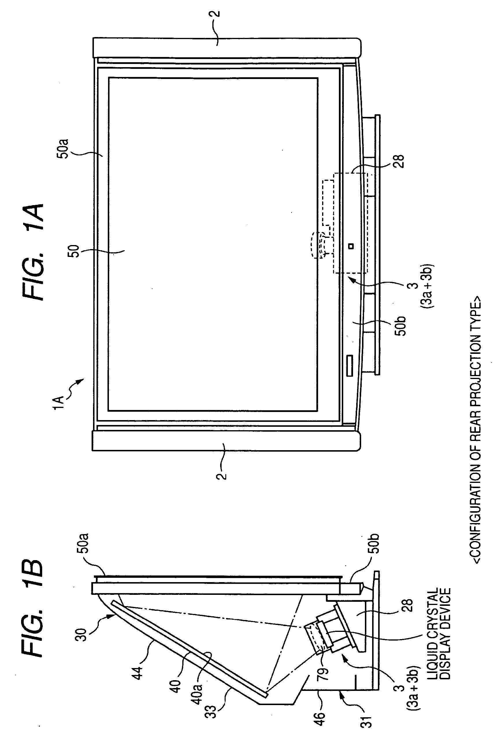
[0075]FIGS. 1A and 1B are diagrams schematically illustrating a projection television as a first example of a rear projection display according to an embodiment of the invention, where FIG. 1A is a front view and FIG. 1B is a side view.

[0076]As shown in FIGS. 1A and 1B, the projection television 1A as the rear projection display includes a frame (a frame of a chassis) 30A and the frame 30A is provided with a projector unit 3 as an example of a projection optical device which is a basic optical system of a projection display, a reflecting mirror 40, and a transmission-type screen 50. A speaker 2 is disposed on both sides of the screen 50. In this example, the frame 30A and the screen 50 constitute the entire chassis. The rear projection display is constructed using the transmission-type screen 50.

[0077]The projector unit 3 serves to output an image-projecting light beam and enlarges and projects an optical image, which is spatially modulated by input...

second example

Projection Display (Second Example)

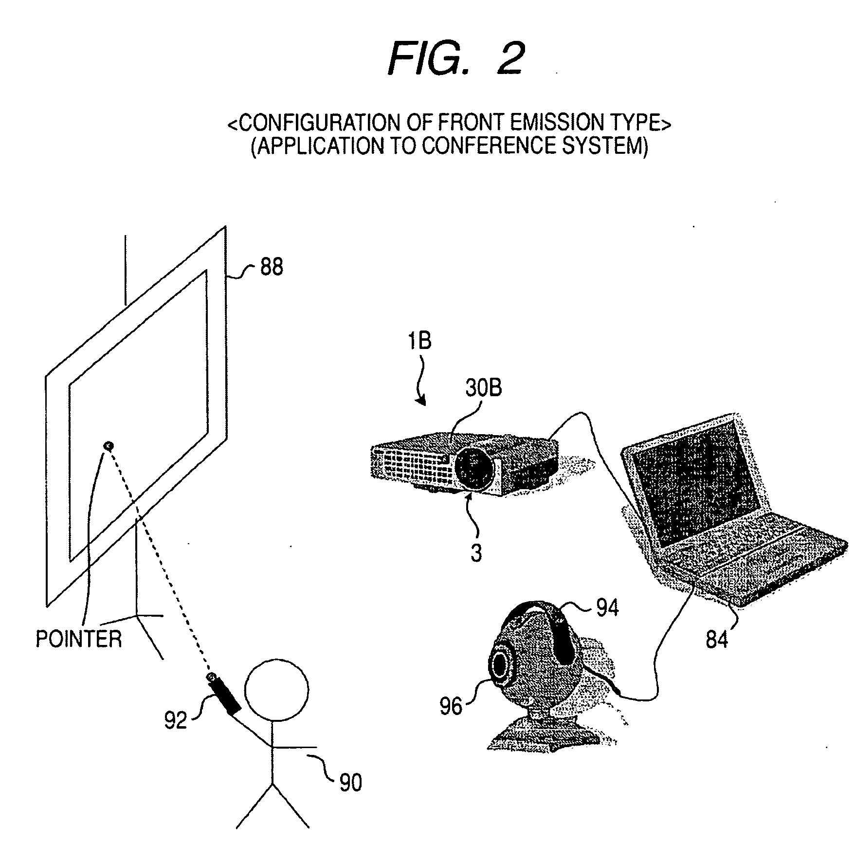
[0088]FIG. 2 is a diagram illustrating the entire configuration of a television conference system as an example of an information providing system employing a second example of the projection display. FIG. 2 shows a configuration of a presenter-side conference room in a usual television conference system. As a structure for displaying image information on a screen, the conference room includes a computer 84 storing a variety of projection image information as conference materials, a liquid crystal projector 1B as a projection device connected to the computer 84, a reflective screen 88 for displaying an image output from the liquid crystal projector 1B, and a laser pointer 92 for displaying a mark as a pointer indicated by the presenter 90 on the information displayed on the screen 88. A front projection display is constructed using the reflective screen 88.

[0089]Similarly to the projection television 1A, a projector unit 3 as an example of the proj...

first embodiment

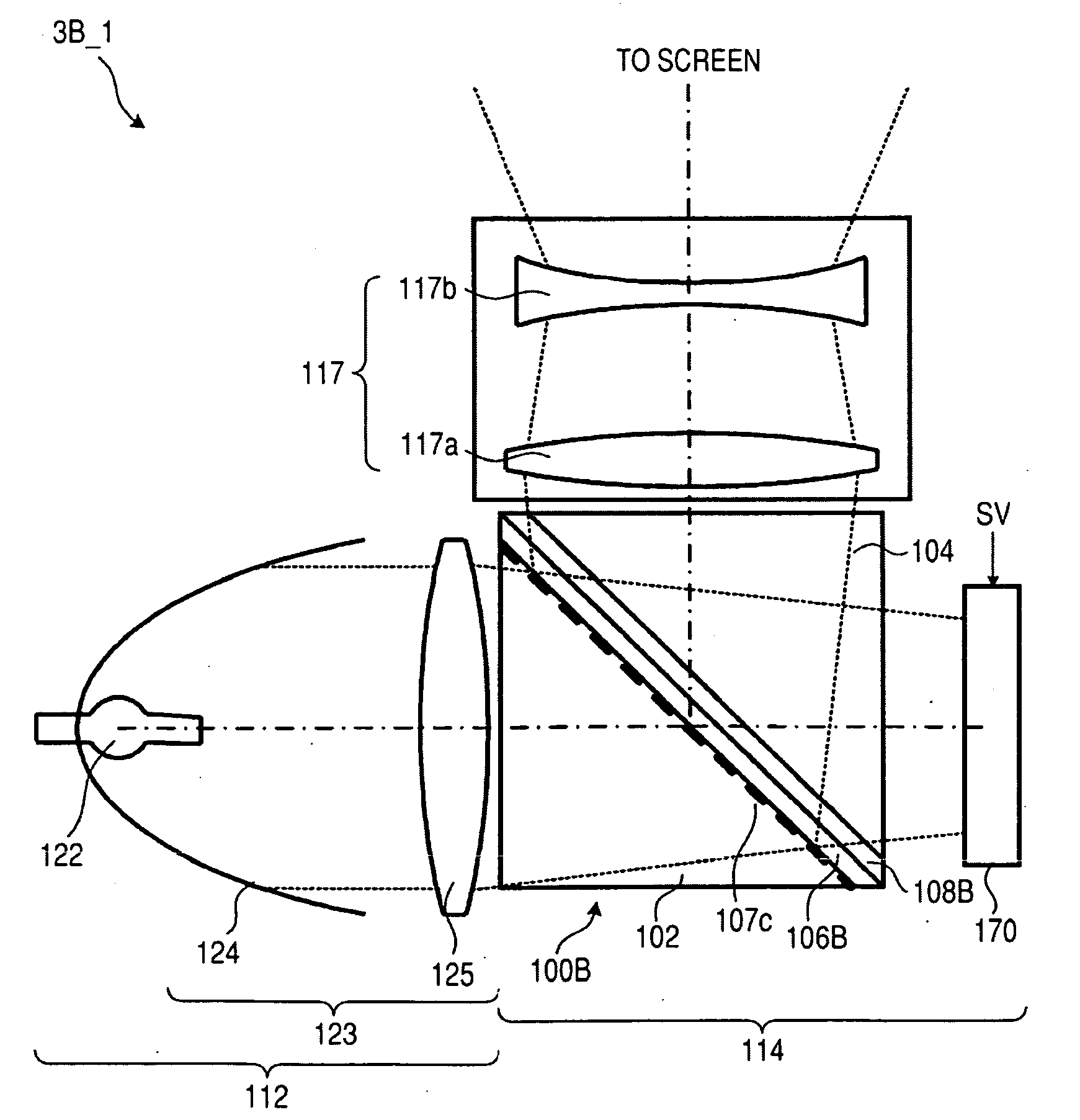
[0101]FIGS. 5A to 7 are diagrams illustrating a basic configuration of a polarizing beam splitter according to a first embodiment of the invention. Here, FIGS. 5A and 5B are diagrams illustrating the entire configuration of the polarizing beam splitter 100A according to the first embodiment. Specifically, FIG. 5A is a perspective view illustrating the entire configuration of the polarizing beam splitter 100A according to the first embodiment and FIG. 5B is a sectional view illustrating the polarizing beam splitter 100A according to the first embodiment in the x-y plane. FIGS. 6A and 6B are diagrams illustrating an operation of the polarizing beam splitter 100A according to the first embodiment. FIG. 7 is a table illustrating optical constants of the polarizing beam splitter 100A according to the first embodiment.

[0102]As shown in FIGS. 5A and 5B, the polarizing beam splitter 100A according to the first embodiment includes triangular glass prisms (prism substrates) 102 and 104 using ...


PUM


Abstract

A polarizing beam splitter includes: first and second prisms each having first and second end surfaces serving as an input surface or an output surface of light and an opposed surface as side surfaces of a pillar-like member; and at least two parallel flat layers disposed in parallel between the opposed surfaces of the first and second prisms. Here, one of the least two parallel flat layers is a first parallel flat layer polarization-separating the input beam. When it is assumed that the refractive index of a base material of the first and second prisms is Np, the resultant refractive index of the parallel flat layers other than the other parallel flat layer of the at least two parallel flat layers is Na, and the refractive index of the other parallel flat layer of the at least two parallel flat layers is Nb, (Na−Np)×(Nb−Np)<0 is satisfied.

Description

CROSS REFERENCES TO RELATED APPLICATIONS[0001]The present invention contains subject matter related to Japanese Patent Application JP 2007-212571 filed in the Japanese Patent Office on Aug. 17, 2007, the entire contents of which is incorporated herein by reference.BACKGROUND OF THE INVENTION[0002]1. Field of the Invention[0003]The present invention relates to an optical prism (a so-called polarizing beam splitter) as an optical member used for a projection optical system for separating polarization by separating an input beam into two linearly-polarized beams perpendicular to each other, transmitting and outputting one polarized beam, and reflecting the other polarized beam, a projection optical device (projection optical system) employing the polarizing beam splitter, and a projection display such as a liquid projector having the projection optical device as a main part or a rear projection display displaying a projected image on a rear projection screen.[0004]2. Description of the...

Claims


Application Information

Patent Timeline
Patent Type & Authority Applications(United States)
IPC IPC(8): G02B27/28G02B27/18G03B21/14
CPCG03B21/14G02B27/283G03B21/2073G03B21/208G03B21/28
Inventor SUNAGA, TOSHIHIRO
Owner SONY CORP
Why Eureka
Try Eureka