Optical device with two cylindrically symmetric mirrors

a cylindrical symmetric mirror and optical device technology, applied in the field of optical devices, can solve the problems of inability to make sudden changes of direction, inconvenient viewing angle, and inability to observe the direction in a continuous manner, and achieve the effect of not inducing and limiting astigmatism

Inactive Publication Date: 2015-04-28
SCHUTZ RONALD JOSEPH
View PDF6 Cites 0 Cited by
  • Summary
  • Abstract
  • Description
  • Claims
  • Application Information

AI Technical Summary

Benefits of technology

[0008]Despite past failure, it is possible by employing two cylindrical mirrors to produce an apparatus with a relatively wide viewing angle, that does not induce spatial confusion and that does not require wide projection from the user. Such advantageous results are achieved by limiting astigmatism, maintaining a magnification in the vertical direction over the whole viewing angle of the device at approximately unity, but allowing the magnification in the horizontal direction to vary, e.g., to continuously decrease, as the viewing angle extends further to the side of the observer. Surprisingly, this arrangement despite a variation in horizontal magnification provides a realistic assessment of object distances while also furnishing an impression of objects generally well beyond the typical viewing angle. Thus, it allows objects to be discerned at wide viewing angles without providing a misleading estimate of the object's distance from the viewer.
[0009]The use of a two cylindrical mirror system having varying horizontal magnification and limited astigmatism also permits the apparatus to be placed in an advantageous position, e.g. directly in front of, or slightly above, a bicyclist's eye or relatively close to the side of a truck. Indeed, in the case of a bicycle it is possible by use of the subject invention to view the forward direction with one eye and the rearward direction with the other. Additionally it is possible to design an apparatus within the subject invention by a relatively straightforward iterative process and to manufacture this design using available expedients.

Problems solved by technology

In this situation the traveling direction to the rear of the observer as compared to the front presents further complications associated with the difficulty in making sudden changes of direction.
This difficulty makes essentially continuous observation of direction crucial.
This constricted viewing angle presents many inconveniences and even some safety issues.
Additionally, in the unfortunate event of an accident the mirror and supporting structure have the potential for being a dangerous projectile.
These difficulties associated with typical bicycle mirrors are certainly not offset by their extremely limited rear viewing angle.
Although the safety concerns previously discussed are not present for rearview equipment in cars, there is a similar limitation on viewing angle.
The presence of such structures well beyond the limits of the vehicle's perimeter at times presents a safety hazard to, for example, pedestrians and at the least, often makes negotiating narrow byways very difficult.
Although this demagnification provides a larger viewing field, it also leads to a misperception of the distance between the viewer and the object being observed.
The resulting difficulties in distance approximation certainly make the act of driving more challenging.
Nevertheless, equipment with multiple flat mirrors still have significant problems such as inversion or rotation of the image, reduced image brightness, added complications, and increased physical size.
Despite an asserted improvement in viewing characteristics, the design procedure for accomplishing the specified characteristics involves multiple limitations including a complicated trial and error design process and a limitation of viewing angle.

Method used


Image

  • Optical device with two cylindrically symmetric mirrors
  • Optical device with two cylindrically symmetric mirrors
  • Optical device with two cylindrically symmetric mirrors

Examples


Embodiment Construction

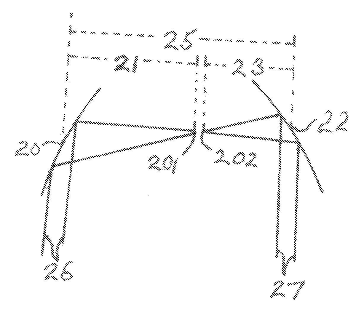
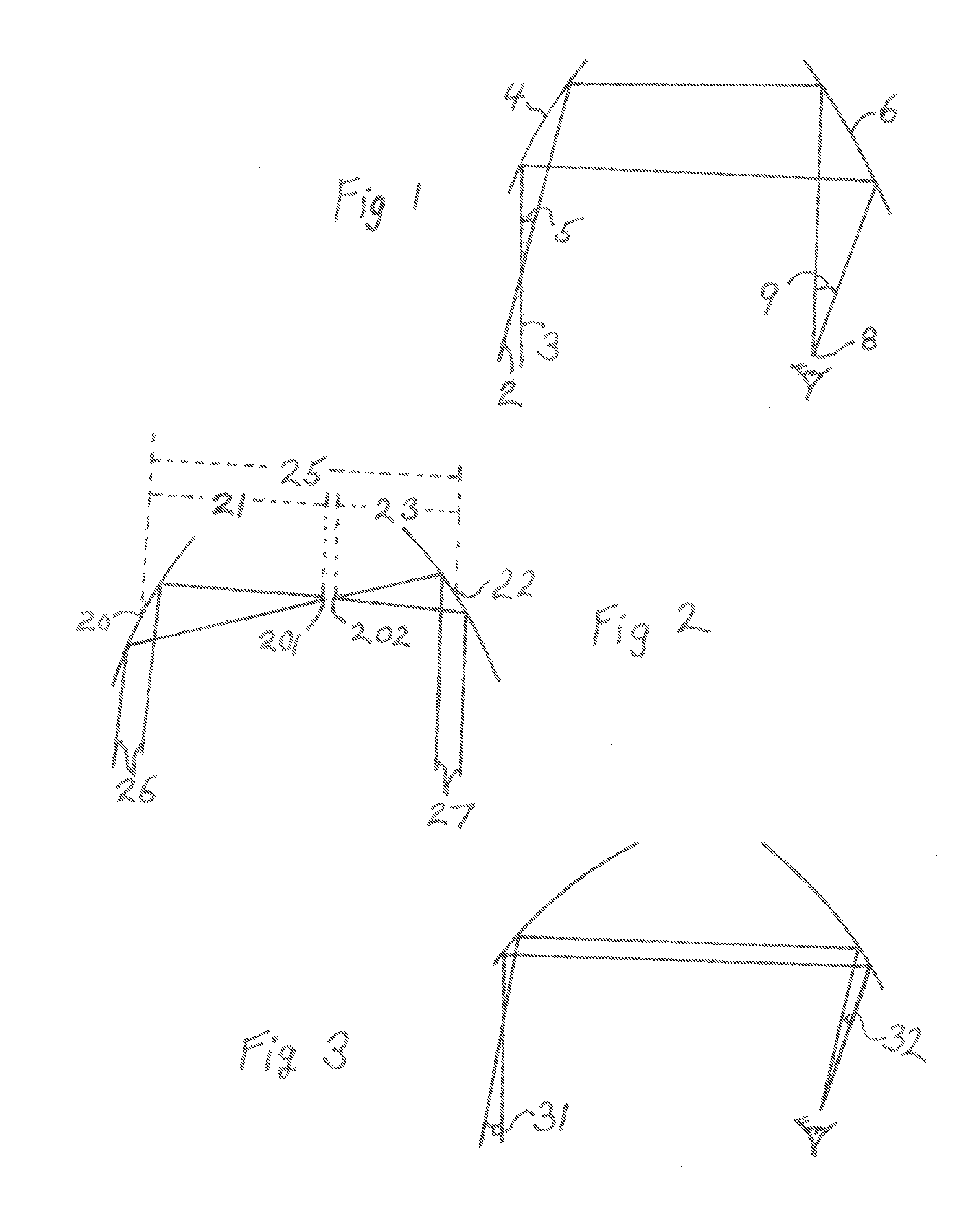
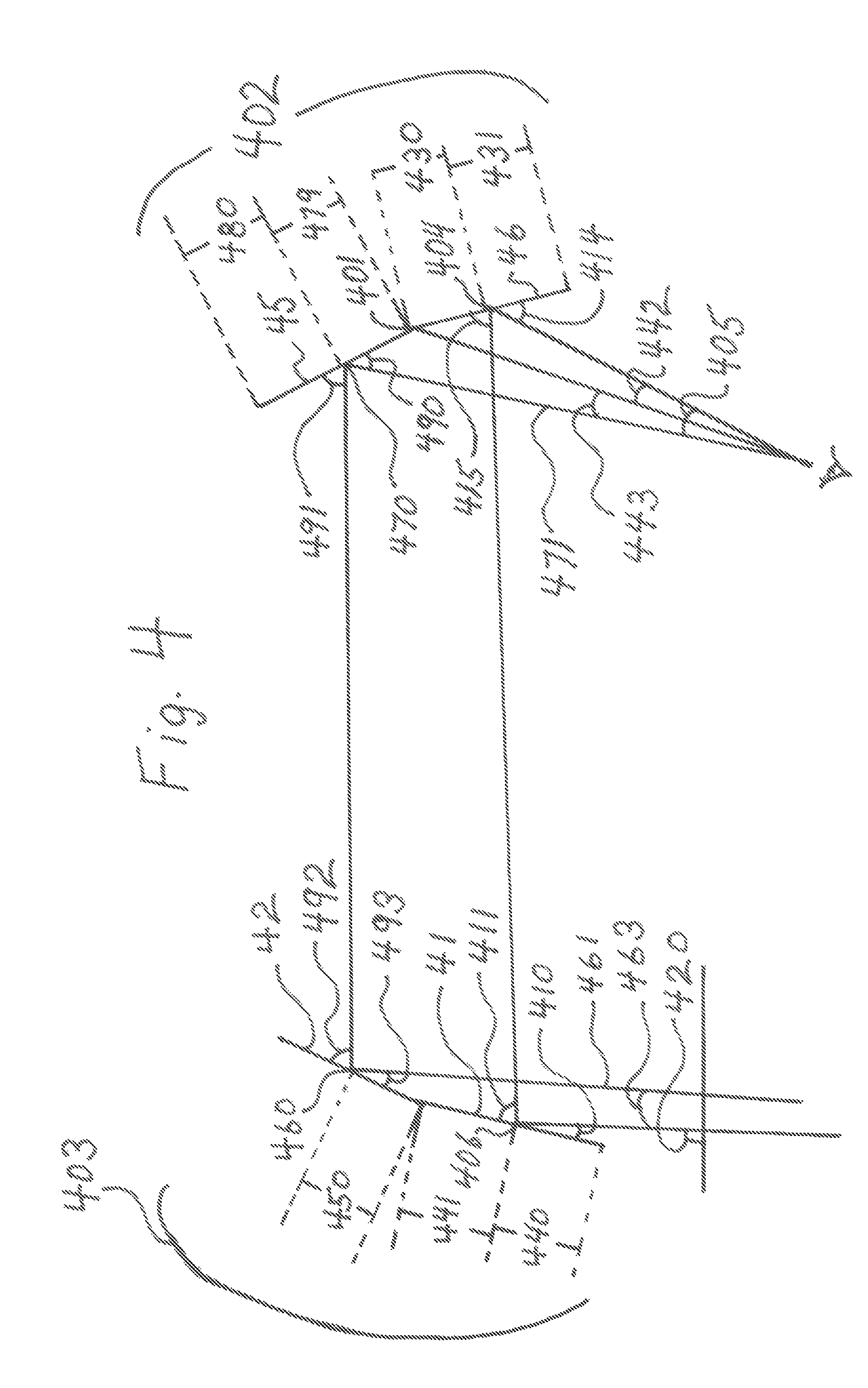
[0013]As discussed, this invention involves an apparatus suitable for viewing a rearward image using at least two mirrors, 1) each of the two having cylindrical symmetry and 2) having a substantially common plane of symmetry. The mirrors are further configured to provide in combination 1) an astigmatism of less than 0.0035, 2) an observable object field of at least 20 degrees, indeed even at least 25 degrees, and 3) a magnification over this field of view that has a ratio of local magnifications (a ratio between A) magnifications far from, relative to B) those close to the contemplated viewer's position) of less than 0.9. In this context, a mirror has cylindrical symmetry if there exists an imaginary plane (denominated the plane of symmetry) that has specific properties. In particular a plane is a plane of symmetry if the intersection of the plane of symmetry (which subsumes planes parallel to this plane) produces curves of intersection with the light-incident surface of the mirror ...


PUM

PropertyMeasurementUnit
viewing angleaaaaaaaaaa
angleaaaaaaaaaa
angleaaaaaaaaaa

Abstract

An advantageous optical apparatus with relatively large field viewing of an image to the rear of an observer is disclosed. The apparatus has two mirrors having cylindrical symmetry where the mirrors are positioned so that a plane of symmetry for each mirror is substantially coincident. The mirrors are further configured so that the apparatus has an astigmatism less than 0.0035, and a ratio between the far field and the near field magnification of less than 0.9. The apparatus is fabricated, in one embodiment, by using force to conform a thin polymer mirror onto an appropriate surface configuration on a monolithic block.

Description

TECHNICAL FIELD[0001]This invention relates to optical devices and more particularly optical devices allowing viewing of an optional field to the rear of an observer.BACKGROUND OF THE INVENTION[0002]Many devices have been developed to allow a user to view an image that is to the user's rear. Common examples of such devises are rear-view mirrors in cars and mirror attachments to bicycle helmets. Another similar but somewhat more demanding use involves viewing a rearward image while, for example, rowing a boat. In this situation the traveling direction to the rear of the observer as compared to the front presents further complications associated with the difficulty in making sudden changes of direction. This difficulty makes essentially continuous observation of direction crucial. Typical viewing approaches have involved essentially flat mirrors mounted in the vicinity of the observer, e.g. side or rear-view mirrors in a car and rear viewing contrivances for a bicycle or small boat.[0...

Claims


Application Information

Patent Timeline
Patent Type & Authority Patents(United States)
IPC IPC(8): G02B17/06B29D11/00B60R1/10
CPCG02B17/0615B29D11/00596B60R1/10
Inventor SCHUTZ, RONALD JOSEPH
Owner SCHUTZ RONALD JOSEPH
Why Eureka
Try Eureka