Equalization of optical signals

Inactive Publication Date: 2007-09-18
AVAGO TECH WIRELESS IP SINGAPORE PTE
View PDF13 Cites 1 Cited by
  • Summary
  • Abstract
  • Description
  • Claims
  • Application Information

AI Technical Summary

Benefits of technology

[0008]Systems and methods of the invention perform time-domain equalization of signals, at least partially, in the optical domain. In this manner, more precise delays can be introduced during equalization than achieved by conventional electrical equalization. Additionally, by optically introducing such delay, i.e., introducin

Problems solved by technology

However, since the pulse width of a light pulse typically is so small, e.g., 25–100 psec, distortions during pulse propagation typically result in the formation of non-ideal pulses.
This can be problematic since non-ideal electrical signals can impair the reliability of the opt

Method used


Image

  • Equalization of optical signals
  • Equalization of optical signals
  • Equalization of optical signals

Examples


first embodiment

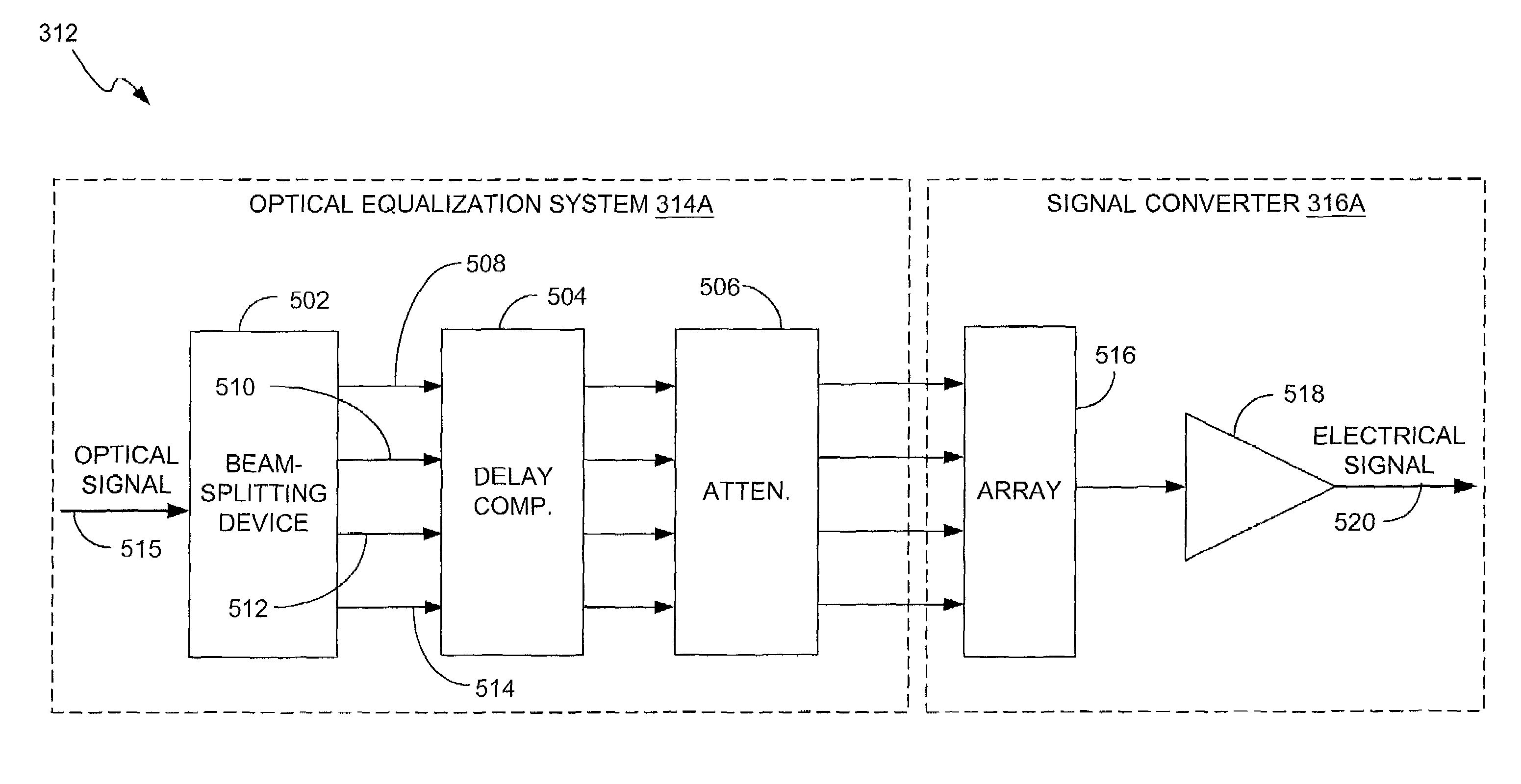
[0032]equalization system 312 is depicted in FIG. 5. As shown in FIG. 5, equalization system 312 includes an optical equalization system 314A and a signal converter 316A. Optical equalization system 314A incorporates a beamsplitting device (or “beamsplitter”) 502, a delay component 504 and an attenuator 506. The beamsplitting device, delay component and attenuator optically communicate to provide multiple beams to the signal converter. In particular, beamsplitting device 502 produces beams 508, 510, 512, and 514 in response to receiving an input optical signal (represented by arrow 515). In some embodiments, each of the beams is a copy of the input optical signal. It should be noted that although four beams are depicted in FIG. 5, various other numbers of beams can be used.

[0033]Beamsplitting device 502 provides beams 508, 510, 512, and 514 to delay component 504. Preferably, delay component 504 differentially delays each of the beams and then provides the beams to attenuator 506. A...

second embodiment

[0037]equalization system 312 is depicted in FIG. 7. As shown in FIG. 7, equalization system 312 includes an optical equalization system 314B and a signal converter 316B. Optical equalization system 314B incorporates a beamsplitting device 702, a delay component 704 and an array of photodetectors 716. The beamsplitting device and delay component optically communicate to provide multiple beams to the signal converter. In particular, beamsplitting device 702 produces beams 708, 710, 712, and 714 in response to receiving an input optical signal (represented by arrow 715). In some embodiments, each of the beams is a copy of the input optical signal. It should be noted that although four beams are depicted in FIG. 7, various other numbers of beams can be used.

[0038]Beamsplitting device 702 provides beams 708, 710, 712, and 714 to delay component 704. Preferably, delay component 704 differentially delays each of the beams and then provides the beams to array 716. More specifically, each o...

third embodiment

[0047]the equalization system 312 is depicted in FIG. 10. In FIG. 10, equalization system 312 includes an optical equalization system 314C and a signal converter 316C. The optical equalization system 314C includes a beamsplitting device 1002, a delay component 1004, and an attenuator 1006. An input optical signal, represented by arrow 1007, is provided to beamsplitting device 1002. In response to the input optical signal, beamsplitting device 1002 produces pairs of beams, e.g., pairs 1008A, 1008B, 1010A, 1010B, 1012A, 1012B, and 1014A, 1014B. Each of the pairs of beams is provided to and differentially delayed by delay component 1004. Preferably, delay component 1004 provides an equivalent, predetermined delay to each beam of a pair of beams. The pairs of beams then are provided to attenuator 1006, which optically scales at least one of the beams. In the embodiment of FIG. 10, attenuator 1006 is configured to provide a fixed attenuation to each of the beams. In other embodiments, ho...


PUM


Abstract

Methods for performing time-domain equalization of an information signal represented by an optical signal are provided. A representative method includes: receiving the optical signal; optically splitting the optical signal into beams; optically delaying at least one of the beams; detecting a plurality of the beams to generate respective electrical signal components; and combining a plurality of the electrical signal components to generate an electrical output signal representing the information signal. Systems and other methods also are provided.

Description

FIELD OF THE INVENTION[0001]The present invention generally relates to communications. More specifically, the invention relates to equalization of signals propagated via communications systems.DESCRIPTION OF THE RELATED ART[0002]Optical communication systems tend to offer greater capacity or “bandwidth” than entirely electrically-based communication systems. However, even current optical communication systems typically use electrical signals and light pulses to communicate information. In particular, transmit components of such an optical communication system convert electrical signals into light pulses. These light pulses are propagated via an optical circuit that defines one or more optical paths. Receive components communicating with the optical paths convert the light pulses back to electrical signals.[0003]A representative optical communication system 100 is depicted schematically in FIG. 1. Optical communication system 100 generally includes an electrical domain 102 and an opt...

Claims


Application Information

Patent Timeline
IPC IPC(8): H04B10/00H04B3/06H04B10/2507
CPCH04B10/2507
Inventor NISHIMURA, KEN A.LEMOFF, BRIAN E.HOKE, CHARLES
Owner AVAGO TECH WIRELESS IP SINGAPORE PTE
Why Eureka
Try Eureka