
Disk tray for disk drive adopting resonator and disk drive having the same

Inactive Publication Date: 2007-09-18
SAMSUNG ELECTRONICS CO LTD
View PDF18 Cites 2 Cited by
  • Summary
  • Abstract
  • Description
  • Claims
  • Application Information

AI Technical Summary

Benefits of technology

[0014]It is an aspect of the present invention to provide a disk drive having a structure that reduces or removes the dominant noise frequency band which occurs at the peak sound pressure level, from the noise in the disk drive, and also to reduce the overall level of noise.
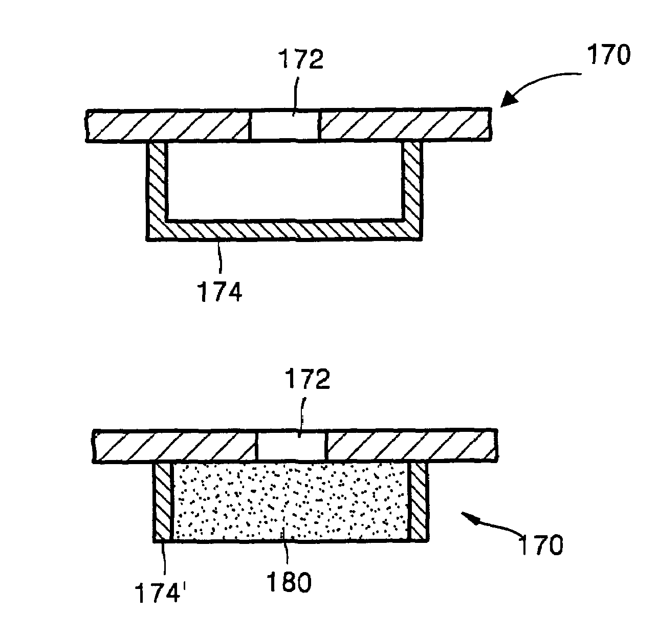
[0016]To achieve the above and / or other aspects according to the present invention, there is provided a disk tray for a disk drive that slides in and out of the disk drive, the disk tray including one or more resonators mounted on a lower surface of the disk tray to selectively reduce noise of a predetermined frequency band.
[0017]To achieve the above and / or other aspects according to the present invention, there is provided a disk drive including a disk tray that slides in and out of the disk drive and on which a disk is placed, a disk driving portion rotating the disk at a predetermined speed, a disk chucking apparatus holding the disk on the disk driving portion, a data recording / reproducing unit recording data on the disk or reproducing data from the disk, and one or more resonators installed on a lower surface of the disk tray to selectively reduce noise of a predetermined frequency band.

Problems solved by technology

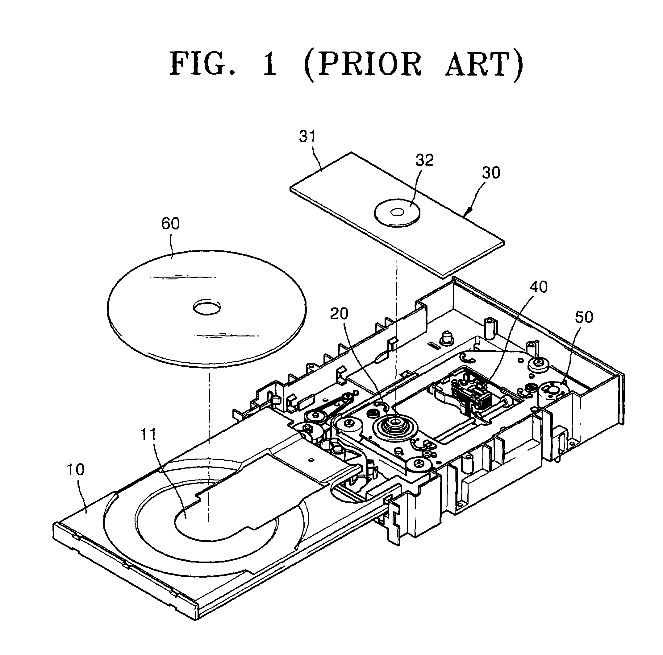
However, vibration is generated due to the rotating disk 60 that deteriorates the recording and reproduction feature of the disk drive.
Further, as the rotation speed of the disk drive increases, the vibration generated during the rotation of the disk 60 impacts reliability in recording and reproduction of data.
Also, noise generated during the rotation of the disk 60 is unpleasant to users.
However, the conventional technologies focus only on the reduction of a level of the overall noise.

Method used


Image

  • Disk tray for disk drive adopting resonator and disk drive having the same
  • Disk tray for disk drive adopting resonator and disk drive having the same
  • Disk tray for disk drive adopting resonator and disk drive having the same

Examples


Embodiment Construction

[0029]Hereinafter, an embodiment of the present invention will be described in detail with reference to the attached drawings, wherein the like reference numerals refer to the like elements throughout. The present invention may, however, be embodied in many different forms and should not be construed as being limited to the embodiment set forth herein; rather, this embodiment is provided so that the present disclosure will be thorough and complete, and will fully convey the concept of the invention to those skilled in the art.

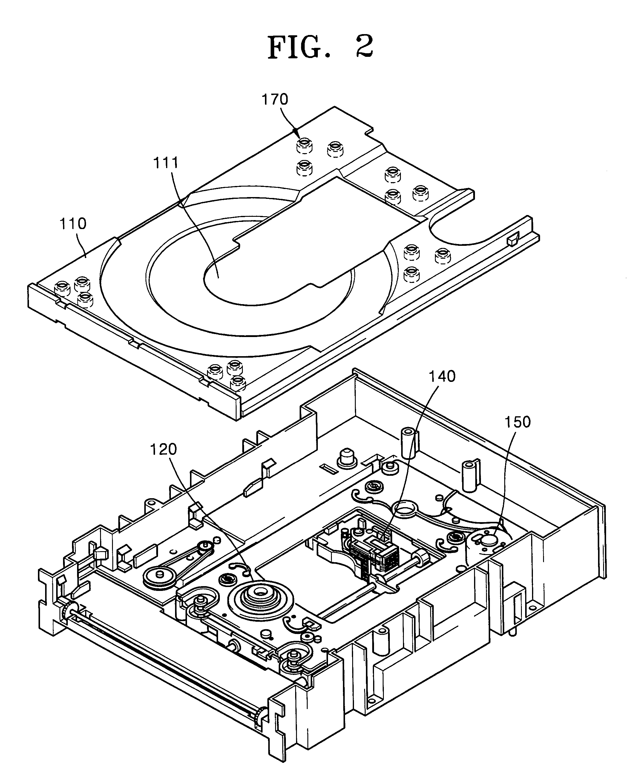
[0030]Referring to FIG. 2, a disk drive according to the present invention includes a disk tray 110, a disk driving portion 120, a disk chucking apparatus (not shown), a data recording / reproducing unit such as an optical pickup device 140, and an optical pickup device driving portion 150.

[0031]The disk tray 110 slides in and out of the front of the disk drive and a disk (not shown) is placed thereon to be loaded or unloaded. The disk driving portion 120 include...


PUM


Abstract

A disk tray for a disk drive that slides in and out of the disk drive, one or more resonators mounted on a lower surface of the disk tray to selectively reduce noise of a predetermined frequency band. According to the present invention, the dominant resonance noise frequency band, which occurs at the peak sound pressure level, is reduced or removed from the noise generated in the disk drive. Also, by filling a resonance container of the resonator with a porous member, the high frequency noise band and the overall noise level can be reduced.

Description

CROSS-REFERENCE TO RELATED APPLICATIONS[0001]This application claims the benefit of Korean Patent Application No. 2002-38664, filed Jul. 4, 2002, in the Korean Intellectual Property Office, the disclosure of which is incorporated herein in its entirety by reference.BACKGROUND OF THE INVENTION[0002]1. Field of the Invention[0003]The present invention relates to a disk drive, and, more particularly, to a disk tray with a resonator to reduce noise and vibration, such as noise generated during rotation of a disk.[0004]2. Description of the Related Art[0005]FIG. 1 is a perspective view of a conventional disk drive. In general, disk drives are apparatuses for either recording information on a recording surface of a disk having concentric tracks, or reading information from the recording surface. Referring to FIG. 1, the disk drive records data on the recording surface of a disk 60 rotating with a linear velocity, or reads data from the recording surface of the disk 60, by using a data rec...

Claims


Application Information

Patent Timeline
IPC IPC(8): G11B33/02G11B17/04G11B33/08
CPCG11B17/056G11B33/08
Inventor CHOI, MYUNG-RYULHONG, SOON-KYO
Owner SAMSUNG ELECTRONICS CO LTD
Learn More