

Adjustable throw-lever picatinny rail clamp
a technology of swan and rail clamp, which is applied in the direction of construction fastening devices, mechanical devices, fastening means, etc., can solve the problem of not being able to adjust the throw lever of swan
- Summary
- Abstract
- Description
- Claims
- Application Information
AI Technical Summary
Benefits of technology
Problems solved by technology
Method used
Image

Examples
Embodiment Construction
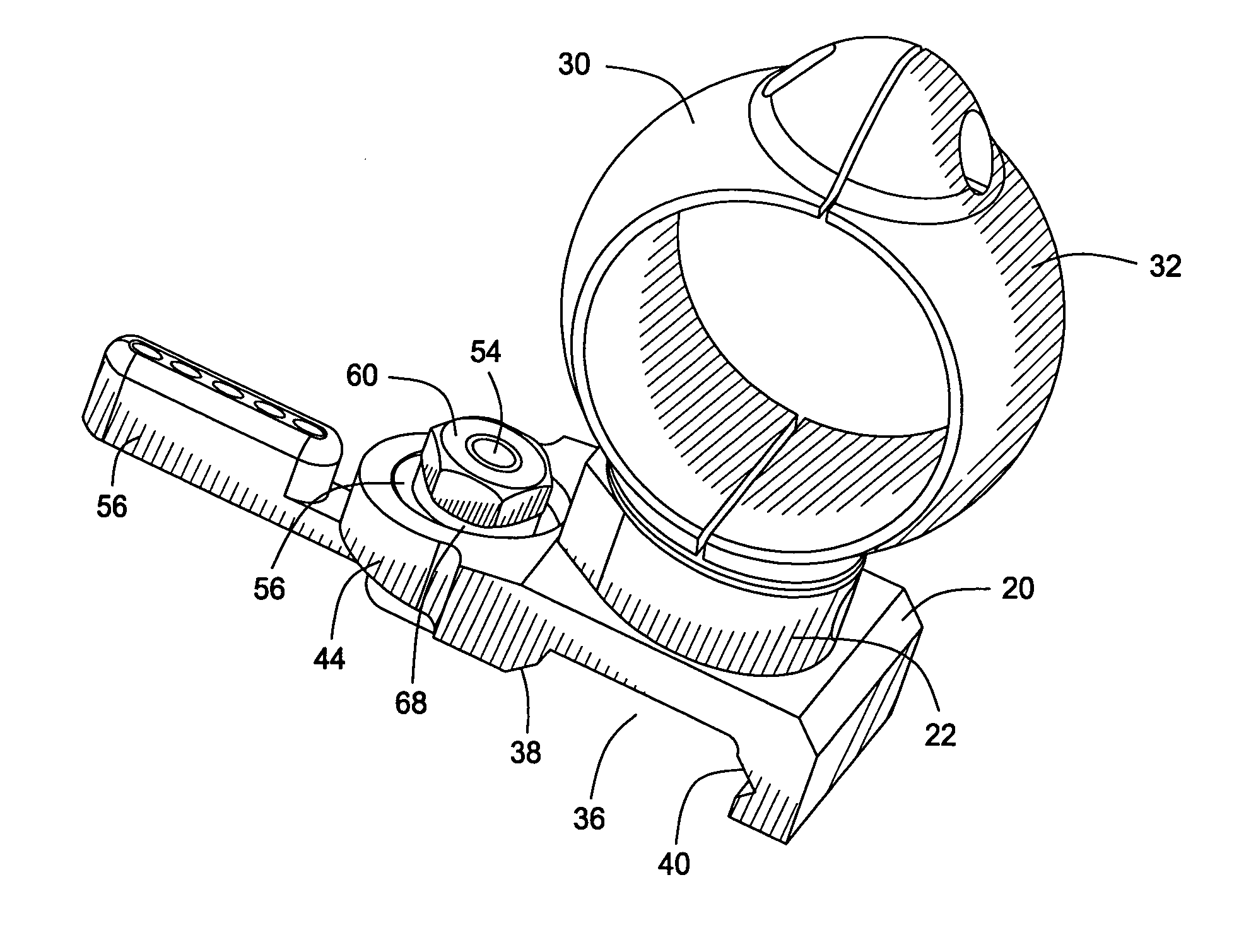
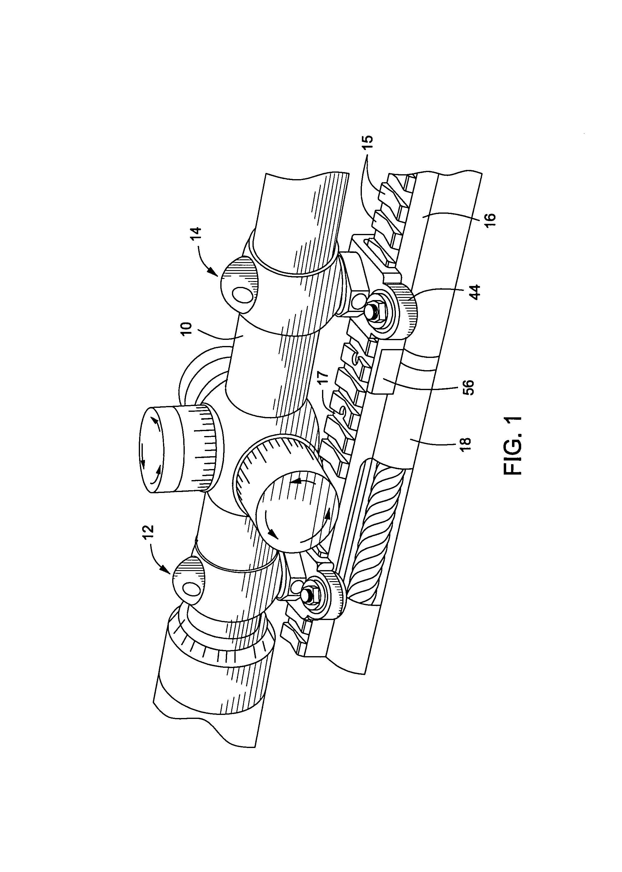
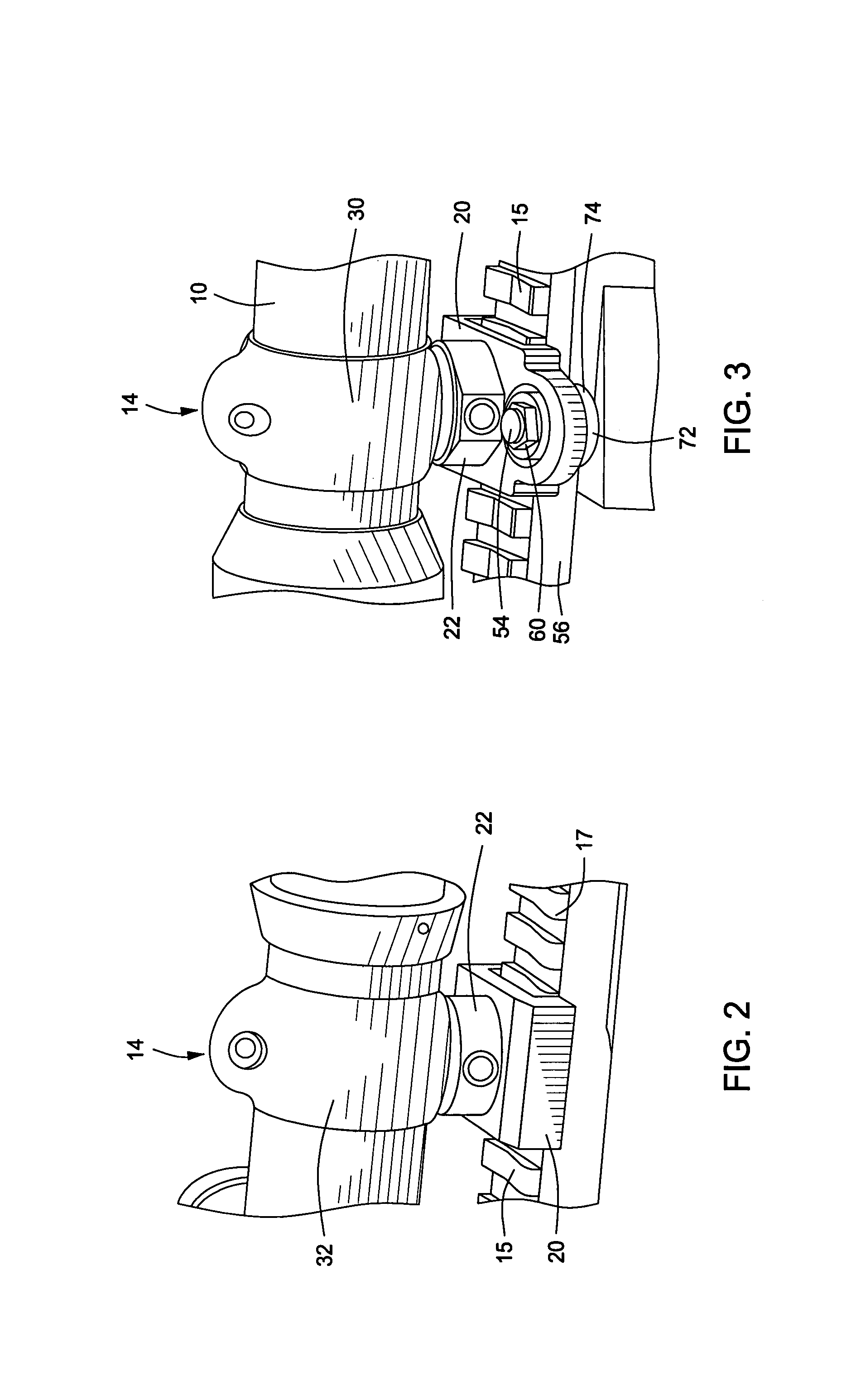
[0038]Though the present invention is discussed herein particularly as it relates to releasable mounts for firearms, particularly tactical rifles used by military and law enforcement personnel, it is to be understood that this invention has application for support of devices other than optical sighting devices on other objects. Referring now to the drawings and first to FIG. 1, an optical sighting device 10, such as a sighting telescope, is supported by front and rear mounting ring assemblies, shown generally at 12 and 14, that mount the sighting device on a mounting rail 16, such as a Picatinny rail or a Weaver rail or the like which is affixed to a firearm 18 or other object. The rail 16 defines a number of evenly spaced upwardly extending mounting projections 15 with evenly spaced transverse slots 17 therebetween to provide for selective location of an optical device on the firearm. As is evident in FIG. 7, each of the spaced upwardly extending mounting projections defines underc...
PUM
 Abstract
Description
Claims
Application Information