Spanner socket

a spanner and socket technology, applied in the field of spanner sockets, can solve the problems of prone to loss, damage and wear of spanner tools, requiring substantial costs, and maintaining a large and bulky tool collection, and achieving the effect of convenient removal and reconfiguration, and simple compact design

Inactive Publication Date: 2007-09-25
PONTIERI JAMES MATTHEW
View PDF27 Cites 31 Cited by
  • Summary
  • Abstract
  • Description
  • Claims
  • Application Information

AI Technical Summary

Benefits of technology

[0012]An object of the present invention is to develop a low cost spanner socket suitable for use by itself or, preferably with a traditional socket wrench. Drive pins designed to engage and apply torque to a work piece such as a spanner nut can be replaced when worn, and readjusted, reconfigured and reoriented for specific applications, giving the tool great utility and flexibility of use.
[0014]As an additional feature, the spanner socket's base member has a axial passage formed there through for receiving apportion of the driving tool as well as providing a recess for receiving an axially extending central portion of a work piece. This arrangement provides a simple compact design, which is extremely robust structurally.
[0015]According to another aspect of the invention, the spanner socket's base member has circumferentially disposed flats arranged on the external surface thereof to provide for use of external force multipliers, such as adjustable wrenches. This arrangement provides additional flexibility and utilitarian design.
[0016]According to another aspect of the invention, each drive pin includes a stepped shank portion adapted for engaging a parallel bore within the base member, a work piece engaging portion having a characteristic cross-sectional dimension somewhat smaller than that of the shank portion and a head portion having a characteristic cross sectional dimension somewhat larger than that of the shank portion. This arrangement provides a design to facilitate easy removal and reconfiguration of drive pin sets and means for precisely limiting axial positioning of each drive pin with respect to the base member.
[0018]According to yet another aspect of the invention, the base member is formed in two or more discrete pieces which preferably comprise an inner ring member removably nestingly engaging with a substantially concentric outer ring member for rotation therewith, wherein the outer ring member carries said drive pins and both of the ring members define engagement surfaces for affixation with a driving tool. This arrangement has the advantage of allowing the base member to be reconfigured for use with different types of driving tools and with different configurations of work pieces.

Problems solved by technology

They have proven to be especially useful in applications where traditional open or closed wrenches, crescent wrenches, pliers and the like cannot be useful due to interference from nearby structures or the need for the application of extremely high levels of torque to the associated mechanical fastening device.
Thus, over time they will be obligated to incur substantial costs as well as maintain a large and bulky tool collection.
These spanner tools are prone to loss, damage and wear.
But in their case frequently suffer from poor design and quality as the manufacturer focuses on low cost processes.
In both cases, a lost, worn or defective tool can destroy the utility of an expensive power tool.
Lastly, replacement spanner tools can be difficult to obtain inasmuch as they are frequently produced by only a single manufacturer.
The spanner wrench according to the '981 patent has the disadvantage that as the tightening nuts become loosened, the drive pins slide along the slots and it is difficult to maintain the proper spacing.
Also, with wear, the drive pins would tend to slide in the slots, thus limiting the usefulness of the wrench.
Further, the range of adjustment is limited to twice the length of the slot.
In many applications where space is limited, such a wrench would not be usable.
The assemblies which effect the adjustability are difficult to adjust with substantial precision and inevitably tend to loosen during use promoting rapid wear.
Furthermore, the long handles typically found on prior art spanner wrenches do not lend themselves to smaller scale applications.
Universal among the above described prior art spanner wrenches are their excessive specialization coupled with their lack of robust design suitable for application of large torque levels while affording great flexibility in downscaling and application in conjunction with other more common hand tools.

Method used


Image

  • Spanner socket
  • Spanner socket
  • Spanner socket

Examples


Embodiment Construction

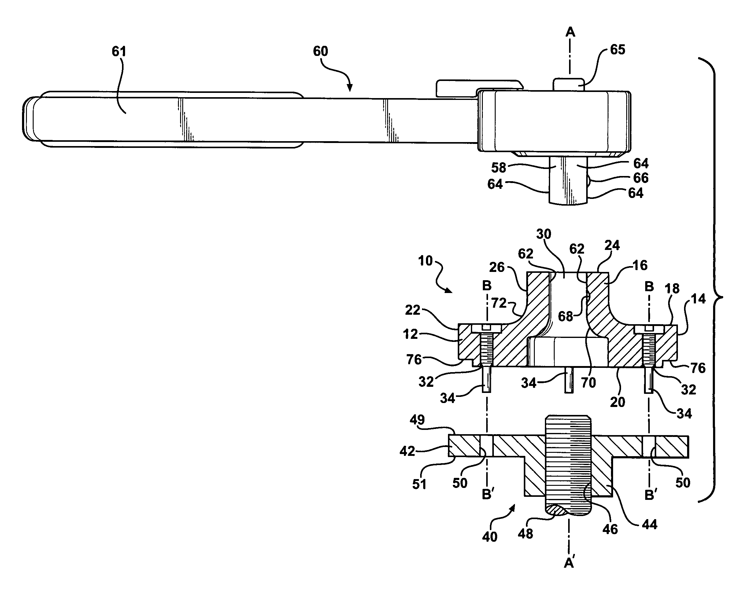
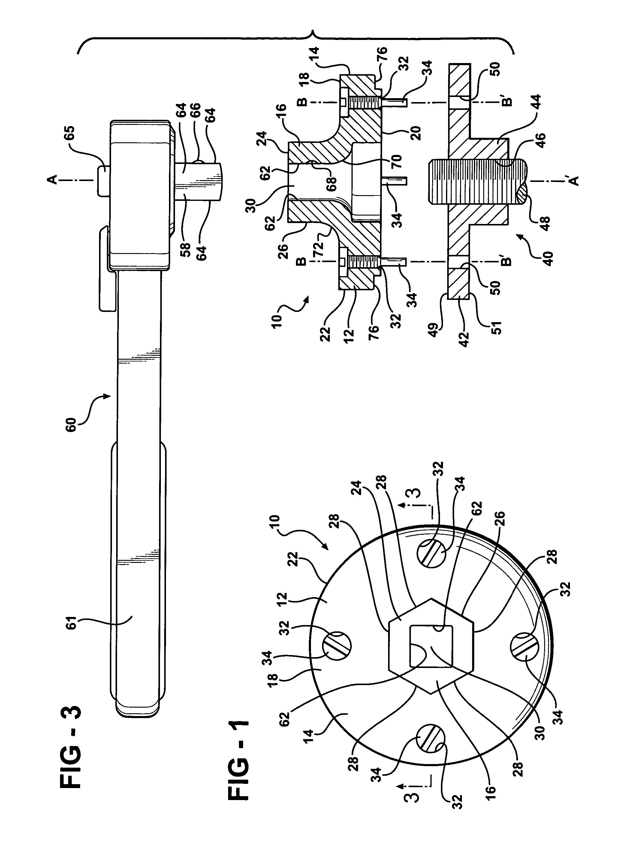
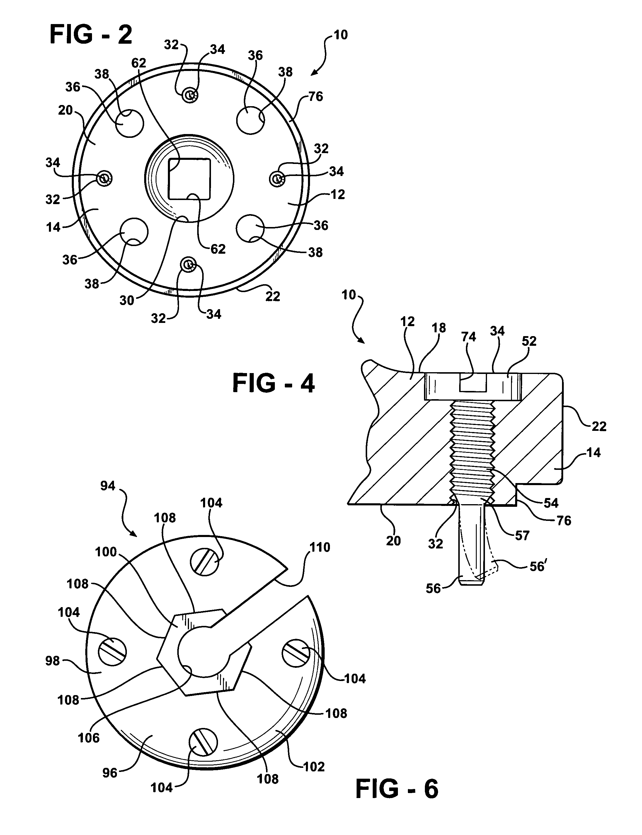
[0029]FIGS. 1 and 2 illustrate a preferred embodiment of the present invention. A spanner socket 10 is constructed as a base member 12 including a generally cylindrical portion 14 and a faceted extension portion 16. Generally cylindrical portion 14 has an upper surface 18, a lower surface 20 and a circumferential outer edge surface 22. Cylindrical portion 14 is symmetrically formed about a vertical axis A-A′ (see FIG. 3). Extension portion 16 is also symmetrically formed about axis A-A′ and extends upwardly from upper surface 18 of cylindrical portion 14. Extension portion 16 has an upper surface 24 and a faceted circumferential outer edge portion 26. Surfaces 18, 19 and 24 are disposed generally parallel to one another and normal to axis A-A′.

[0030]Faceted edge portion 26 defines a number, of radially outwardly facing flats or engagement surfaces 28 of equal size circumferentially arranged around axis A-A′. Preferably, edge portion 26 is formed as a hex-head of standard size such t...


PUM


Abstract

A spanner socket for application with conventional hand tools such as ratchet drivers and fixed wrenches employed for imparting torque to a work piece about an axis of rotation includes a generally cylindrical shaped base member which defines a predetermined number of engagement surfaces which are circumferentially arranged around the axis of rotation. The engagement surfaces are employed for releasably coupling with the associated hand tool. Two or more elongated drive pins are carried by the base member for rotation therewith about said axis of rotation. Each drive pin defines an axis of elongation, which is parallel to the axis of rotation and spaced from the axis of rotation for engagement with the work piece for the application of torque thereto.

Description

[0001]The present invention relates generally to spanner wrenches, i.e. wrenches having a pair of projections which may be engaged in spaced apart holes, slots, notches or other forms of tool receiving recesses formed in an article to be turned. More specifically, the present invention relates to devices adaptable for use which conventional standard hand tools to manipulate threaded nuts, collets, ferrules and similar mechanical fastening devices.BACKGROUND OF THE INVENTION[0002]Spanner wrenches of various forms and configurations have been in use for many years. They have proven to be especially useful in applications where traditional open or closed wrenches, crescent wrenches, pliers and the like cannot be useful due to interference from nearby structures or the need for the application of extremely high levels of torque to the associated mechanical fastening device. Frequently, spanner wrenches are designed for a specific application, such as applying torque axially to a mechani...

Claims


Application Information

Patent Timeline
Patent Type & Authority Patents(United States)
IPC IPC(8): B25B13/48B25B13/28B25B13/58
CPCB24B45/003B25B13/481B25B13/485B25B13/50
Inventor PONTIERI, JAMES MATTHEW
Owner PONTIERI JAMES MATTHEW
Why Eureka
Try Eureka