Planetary-roller-type continuously variable transmission

a technology of continuously variable transmission and roller, which is applied in the direction of gearing details, mechanical equipment, gearing, etc., can solve the problem of not being able to obtain the predetermined rotation speed ratio between the output shaft and the output shaft, and achieve the effects of low noise, high rigidity and high efficiency

Inactive Publication Date: 2007-09-25
MITSUBISHI HEAVY IND LTD
View PDF33 Cites 8 Cited by
  • Summary
  • Abstract
  • Description
  • Claims
  • Application Information

AI Technical Summary

Benefits of technology

[0011]2) It is desirable to have a power transmission device that can increase and decrease the rotation speed ratio within a relatively small range depending on the operating conditions, for example, reducing the rotation speed ratio in the event of the rotation speed of the input shaft becoming too large, or increasing the rotation speed ratio in the event of the rotation speed of the input shaft becoming too small.
[0039]A high-quality planetary-roller-type continuously variable transmission that realizes power transmission is provided; the continuously variable transmission is compact, produces low noise, and has high rigidity, high efficiency, and extremely low angular transmission error.

Problems solved by technology

For example, in the case where the driving mechanism is an electric motor, when changes occur in the operating environment, such as the voltage supplied to the electric motor, it may not be possible to obtain the predetermined rotation speed ratio between the output shaft of the electric motor and the input shaft of the mechanism being driven.

Method used


Image

  • Planetary-roller-type continuously variable transmission
  • Planetary-roller-type continuously variable transmission
  • Planetary-roller-type continuously variable transmission

Examples


Embodiment Construction

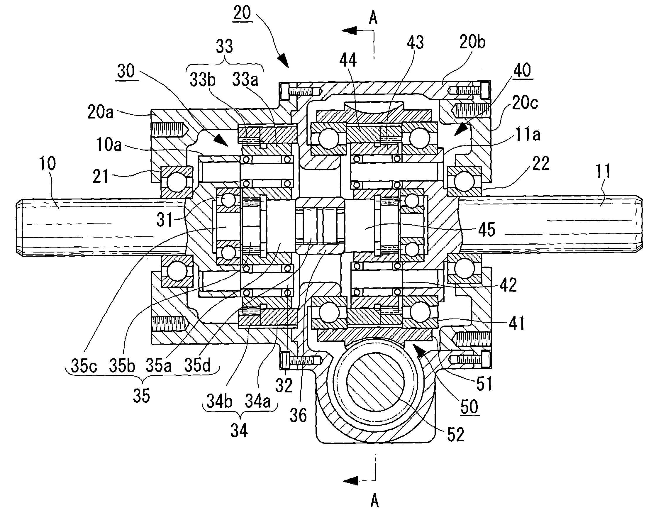
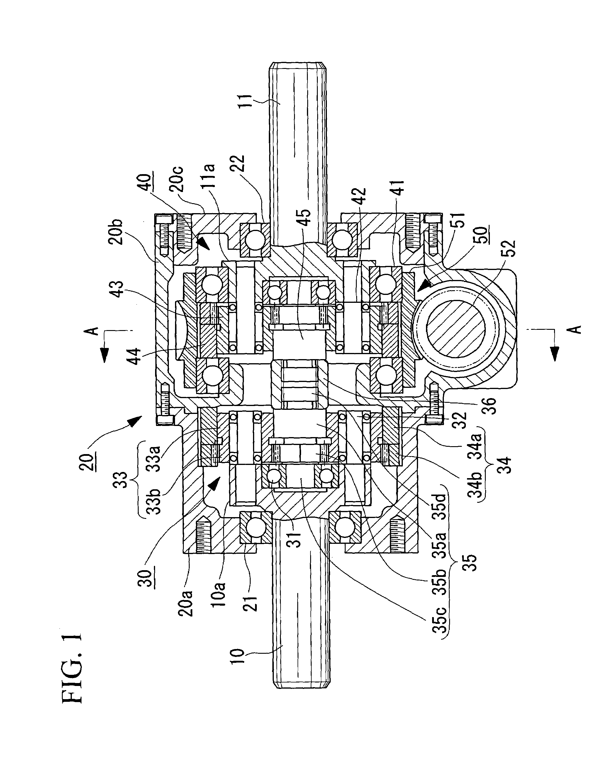
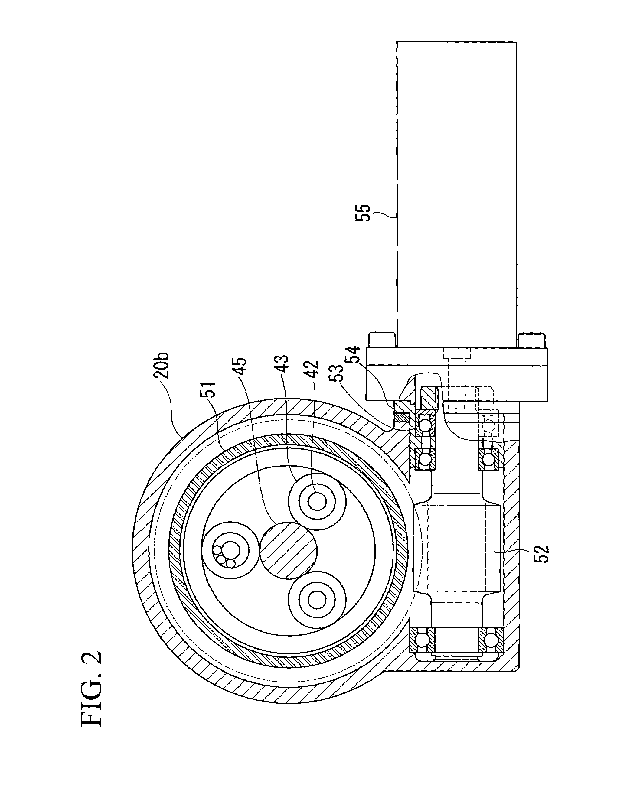
[0043]An embodiment of the planetary-roller-type continuously variable transmission (hereinafter referred to as “continuously variable transmission”) of the present invention will be described with reference to FIG. 1 and FIG. 2.

[0044]FIG. 1 is a front view (longitudinal cross-sectional view) of the continuously variable transmission of the present embodiment, and FIG. 2 is a cross-sectional view (partial exterior view) along A-A in FIG. 1.

[0045]In both figures (referring mainly to FIG. 1), the member indicated by reference numeral 10 is an input shaft connected with a driving mechanism such as, for example, a motor, and the member indicated by reference numeral 11 is an output shaft connected to a mechanism to be driven.

[0046]The member indicated by reference numeral 20 is a substantially cylindrical housing, and this housing 20 is formed of a front housing 20a including a front wall, a rear housing 20b, and a rear cover 20c. The front housing 20a and the rear housing 20b are joine...


PUM


Abstract

Fine adjustment of the rotation speed ratio or intentional control of the rotation speed ratio is carried out, centered on a desired speed ratio, including 1:1, for the rotation speed ratio between an input shaft and an output shaft. A planetary-roller speed-increasing mechanism whose input shaft is a carrier and whose output shaft is a sun roller, a planetary-roller speed-reduction mechanism whose input shaft is a sun roller and whose output shaft is a carrier, and a worm speed-changing mechanism for rotationally driving a roller ring in contact with planetary rollers of the planetary-roller speed reduction mechanism are provided in a housing. The output shaft of the planetary-roller speed-increasing mechanism and the input shaft of the planetary-roller speed-reduction mechanism are linked.

Description

BACKGROUND OF THE INVENTION[0001]1. Field of the Invention[0002]The present invention relates to planetary-roller-type continuously variable transmissions disposed between a driving mechanism and a mechanism being driven, and also relates to planetary-roller-type continuously variable transmissions suitable for use in cases where the rotation speed ratio of the output shaft to the input shaft thereof is minutely adjusted or intentionally controlled, centered around a predetermined speed ratio, including 1:1.[0003]This application is based on patent application No. 2004-173019 filed in Japan, the content of which is incorporated herein by reference.[0004]2. Description of Related Art[0005]Until now, there has been a great demand for continuously variable transmissions. For example, in the case where the driving mechanism is an electric motor, when changes occur in the operating environment, such as the voltage supplied to the electric motor, it may not be possible to obtain the prede...

Claims


Application Information

Patent Timeline
Patent Type & Authority Patents(United States)
IPC IPC(8): F16H13/06F16H1/28F16H15/48F16H3/72
CPCF16H3/724Y10S475/903
Inventor HIROYUKI, SONOBEISAMU, SHIOTSUTAKAYOSHI, HIRAYAMA
Owner MITSUBISHI HEAVY IND LTD
Why Eureka
Try Eureka