Multiple output power supply that configures itself to multiple loads

a power supply and load technology, applied in the direction of electric variable regulation, process and machine control, instruments, etc., can solve the problems of cumbersome use, improper and potentially damaging voltage applied to the electrical device, and confusion of similar, yet different universal ac-to-dc converters, etc., to increase the safety of the electrical device.

Inactive Publication Date: 2007-09-25
MANOLESCU MIHAI COSTIN
View PDF14 Cites 101 Cited by
  • Summary
  • Abstract
  • Description
  • Claims
  • Application Information

AI Technical Summary

Benefits of technology

[0021]The information returned by the electrical device to the DC-ID CNTR can include information about the status of the electrical device. The DC-ID CNTR can use that information for various purposes such as increasing the safety of the electrical device. The status information can include, for example, temperature information. If the status information indicates a problem in the electrical device, the DC-ID CNTR can take corrective action such as turning off the programmable DC voltage supplied to the electrical device.

Problems solved by technology

As a result, the consumer may have a confusing mess of similar, yet different,.
Such universal AC-to-DC converters are, unfortunately, considered cumbersome to use.
In some cases, the switch can inadvertently be moved when the converter is in use, resulting in an improper and potentially damaging voltage being applied to the electrical device.
Moreover, the number of different selectable output voltages is often quite limited due to the expense of providing a large, many position switch to select the output voltage.
In addition to the universal AC-to-DC converter being cumbersome to use, a universal AC-to-DC converter does not provide a simple automatic way of determining whether the AC-to-DC converter will be able to supply enough output current to power a desired electrical device properly.
This is an inconvenient exercise.
Initially, the DC-ID in the electrical device is unpowered.
The power supply device is not supplying DC supply power to the electrical device.

Method used


Image

  • Multiple output power supply that configures itself to multiple loads
  • Multiple output power supply that configures itself to multiple loads
  • Multiple output power supply that configures itself to multiple loads

Examples


Embodiment Construction

[0042]Reference will now be made in detail to some embodiments of the invention, examples of which are illustrated in the accompanying drawings.

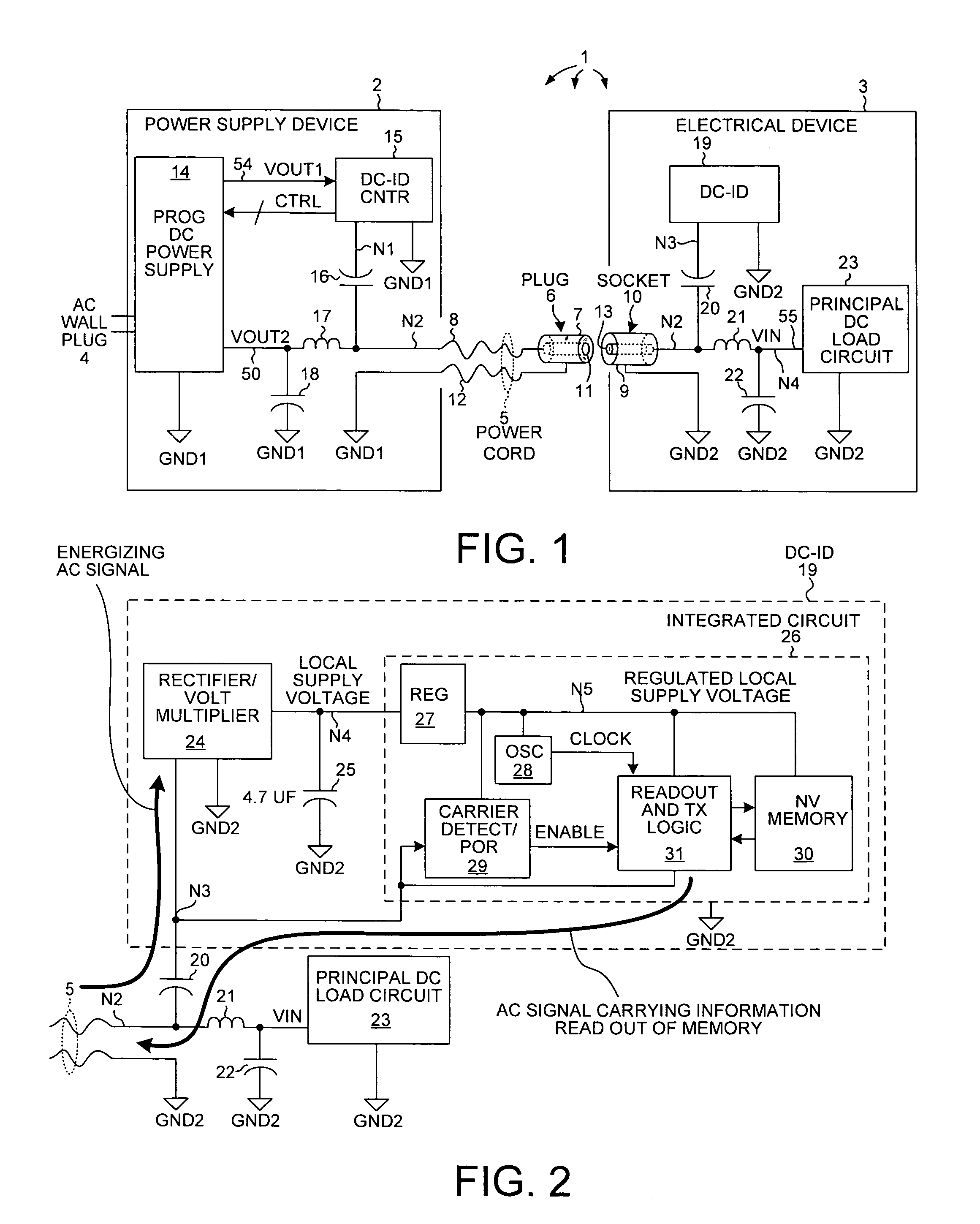
[0043]FIG. 1 is a diagram of a system 1 in accordance with one novel aspect. System 1 includes a power supply device 2 and an electrical device 3. Power supply device 2 includes an AC wall plug 4. When the AC wall plug 4 is plugged into an AC wall socket (not shown), the power supply device 2 draws power from the wall socket. Power supply device 2 also includes a power cord 5 that terminates in a DC power supply connector 6. In the present example, DC power supply connector 6 is a two-contact male barrel plug often used to supply DC power to electrical devices. Plug 6 has an outer barrel-shaped conductive contact 7 that is coupled to a first conductor 8 of the power cord 5. Barrel contact 7 is adapted to engage a female barrel shaped contact 9 of a female two-contact socket 10 of the electrical device. Plug 6 also has a female inner contact ...


PUM


Abstract

A two stage multiple output power supply device is capable of outputting programmable DC voltages onto multiple outputs. The first stage receives an AC supply voltage and outputs a DC supply voltage. The second stage includes a DC-ID controller and multiple DC-to-DC converters, each DC-to-DC converter receiving the DC supply voltage and capable of outputting a programmable DC voltage onto a conductor of a power cord to power an electrical device. For each DC-to-DC converter, the DC-ID controller receives information in an AC signal on the conductor, the information indicating the voltage and current requirements and the polarity of an electrical device connected to the power cord for that DC-to-DC converter. In response to the information, the DC-ID controller controls the DC-to-DC converter to set a magnitude, a polarity and a current limit for the programmable DC voltage that will be output by the DC-to-DC converter.

Description

CROSS-REFERENCE TO RELATED APPLICATION[0001]This application is a continuation-in-part of, and claims the benefit under 35 U.S.C. 120 to, U.S. patent application Ser. No. 11 / 198,288, filed Aug. 3, 2005. The subject matter of U.S. patent application Ser. No. 11 / 198,288 is incorporated herein by reference.BACKGROUND INFORMATION[0002]Small consumer electrical devices (for example, digital cameras, digital music players, cellular telephones, personal digital assistants, laptop computers) typically have a jack or socket for receiving DC (direct current) voltage power. An AC-to-DC converter is typically supplied with the electrical device. The AC-to-DC converter has a wall plug for plugging the AC-to-DC converter into an AC wall socket. The AC-to-DC converter also has a power cord that terminates in a plug. To power the electrical device from power received from the wall socket, the plug of the AC-to-DC converter is plugged into the receiving DC power input socket of the electrical device...

Claims


Application Information

Patent Timeline
Patent Type & Authority Patents(United States)
IPC IPC(8): G05F1/577
CPCH02M3/157H02M3/33515H02M7/103H02M3/33561H02M7/217H02M1/007
Inventor MANOLESCU, MIHAI-COSTIN
Owner MANOLESCU MIHAI COSTIN
Why Eureka
Try Eureka