Maximum ratio transmission

a transmission and maximum ratio technology, applied in the field of maximum ratio transmission, can solve the problems of adverse propagation effect, wireless communication system suffer multipath fading, all wireless communications services are subject to the vagaries of propagation environment, etc., and achieve the effect of improving performan

Inactive Publication Date: 2007-09-25
SONY CORP
View PDF122 Cites 5 Cited by
  • Summary
  • Abstract
  • Description
  • Claims
  • Application Information

AI Technical Summary

Problems solved by technology

That is, regardless of their forms, all wireless communications services are subjected to vagaries of the propagation environments.
The most adverse propagation effect from which wireless communications systems suffer is the multipath fading.
Multipath fading, which is usually caused by the destructive superposition of multipath signals reflected from various types of objects in the propagation environments, creates errors in digital transmission.
Thus, since p<1, combining the signals from several antennas reduces the outage probability of the system.

Method used


Image

  • Maximum ratio transmission
  • Maximum ratio transmission
  • Maximum ratio transmission

Examples


Embodiment Construction

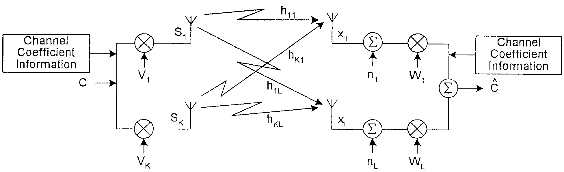
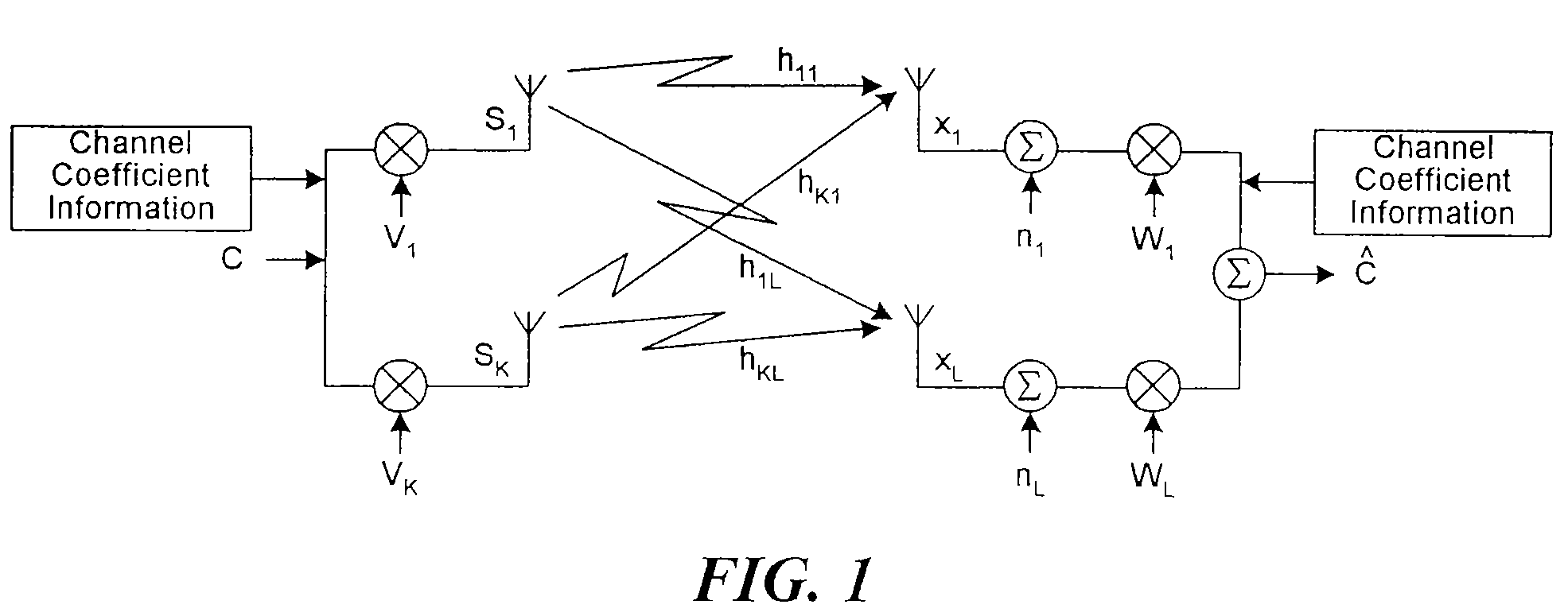
[0012]FIG. 1 depicts a system which comprises K antennas for transmission and L antennas for reception. The channel between the transmit antennas and the receive antennas can be modeled by K×L statistically independent coefficients, as shown in FIG. 1. It can conveniently be represented in matrix notation by

[0013]H=[h11⋯h1⁢K⋮⋰⋮hL1⋯hLK]=[h1⋮hL](1)

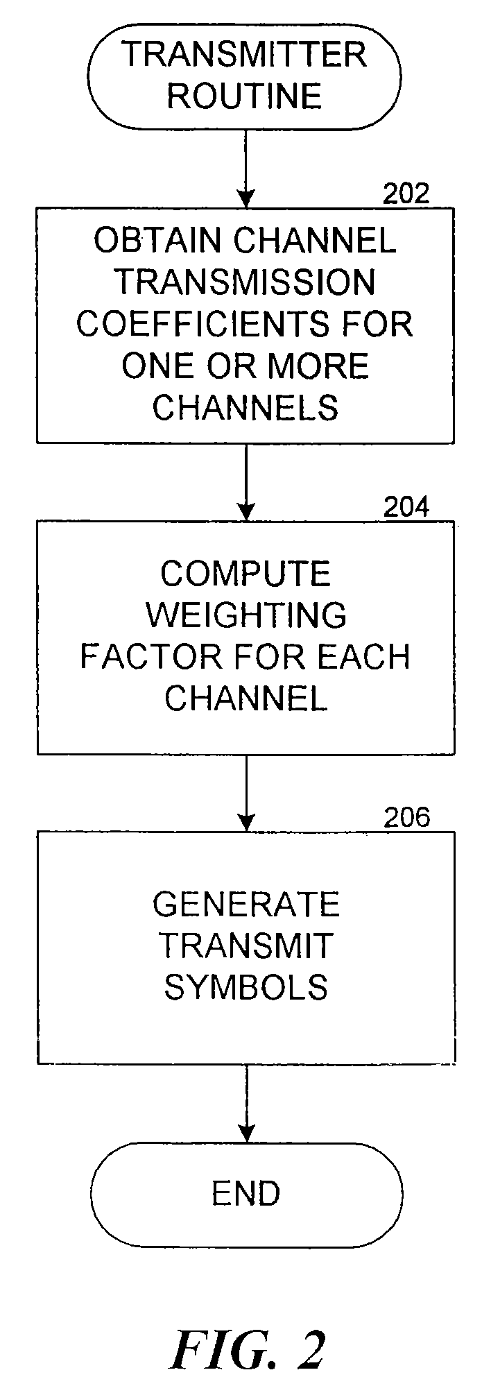
where the entry hpk represents the coefficient for the channel between transmit antenna k and receiver antenna p. It is assumed that the channel coefficients are available to both the transmitter and receiver through some means, such as through a training session that employs pilot signals sent individually through each transmitting antenna (see block 202 of FIG. 2 and block 302 of FIG. 3). Since obtaining these coefficients is well known and does not form a part of this invention, additional exposition of the process of obtaining the coefficients is deemed not necessary.

[0014]The system model shown in FIG. 1, and also in the routines of FIG...


PUM


Abstract

An arrangement where a transmitter has a plurality of transmitting antennas that concurrently transmit the same symbol, and where the signal delivered to each transmitting antenna is weighted by a factor that is related to the channel transmission coefficients found between the transmitting antenna and receiving antennas. In the case of a plurality of transmit antennas and one receive antenna, where the channel coefficient between the receive antenna and a transmit antenna i is hi, the weighting factor is hi* divided by a normalizing factor, α, which is(∑k=1K⁢hk2)1 / 2,where K is the number of transmitting antennas. When more than one receiving antenna is employed, the weighting factor is1a⁢(gH)H,where g=[g1 . . . gL], H is a matrix of channel coefficients, and α is a normalizing factor(∑p=1L⁢∑q=1L⁢∑k=1K⁢hpk⁢hqk*)1 / 2.

Description

CROSS REFERENCE TO RELATED APPLICATIONS[0001]This application is a continuation of U.S. patent application Ser. No. 10 / 177,461, filed on Jun. 19, 2002, now U.S. Pat. No. 6,826,236, which is a continuation of U.S. patent application Ser. No. 09 / 156,066 filed on Sep. 17, 1998, now U.S. Pat. No. 6,459,740, both of which are incorporated herein by reference in their entirety.BACKGROUND OF THE INVENTION[0002]Wireless communications services are provided in different forms. For example, in satellite mobile communications, communications links are provided by satellite to mobile users. In land mobile communications, communications channels are provided by base stations to the mobile users. In PCS, communications are carried out in microcell or picocell environments, including outdoors and indoors. Regardless the forms they are in, wireless telecommunication services are provided through radio links, where information such as voice and data is transmitted via modulated electromagnetic waves...

Claims


Application Information

Patent Timeline
Patent Type & Authority Patents(United States)
IPC IPC(8): H04L27/00H04B7/06H04B7/08H04L1/06H04L25/02
CPCH04B7/0615H04B7/0617H04B7/0626H04B7/0857H04L1/06H04L25/03343H04B7/0842H04L25/0204H04L2025/03426
Inventor LO, TITUS
Owner SONY CORP
Why Eureka
Try Eureka