Plasma anemometer and method for using same

a plasma anemometer and plasma technology, applied in the field of measurement systems, can solve the problems of inability to accurately simulate numerical simulations, inability to develop empirical criteria or validate numerical simulations, and inability to accurately simulate,

Inactive Publication Date: 2007-09-25
UNIV OF NOTRE DAME DU LAC +1
View PDF1 Cites 39 Cited by
  • Summary
  • Abstract
  • Description
  • Claims
  • Application Information

AI Technical Summary

Problems solved by technology

Despite the needs for mass-flux measurements in these environments, there is little accurate data with which to develop empirical criteria or to validate numerical simulations that might be used in the design of new equipment.
The difficulty largely comes from the extreme experimental regime that includes high aerodynamic (steady and dynamic) loads, high temperatures, small scales, and large gradients in the measured quantities.
At compressible Mach numbers, this simplification is not accurate, and the effect of all three independent quantities needs to be accounted for in the sensitivity response function of the sensor.
This greatly complicates the procedure for calibration of the sensor.
However, they are very fragile, especially when compared to hot-film probes.
Further problems with surface-mounted sensors, such as hot-films, include a possible severe mismatch in thermal expansion coefficients between the sensor and substrate materials that can lead to damaging mechanical stresses in the substrate, even in moderate-enthalpy hypersonic facilities.
However, these anemometers were limited to frequencies below 700 kHz, which limits frequency response and bandwidth of the sensor.
Further, these anemometers were large and cumbersome and not practical for measurements of high speed flows requiring high spatial resolution.
Nor were they operated in a constant current mode, which is necessary to maximize sensor response.

Method used


Image

  • Plasma anemometer and method for using same
  • Plasma anemometer and method for using same
  • Plasma anemometer and method for using same

Examples


Embodiment Construction

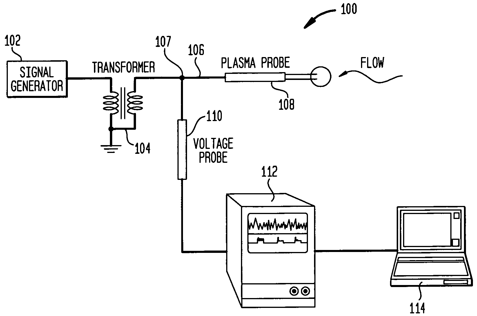
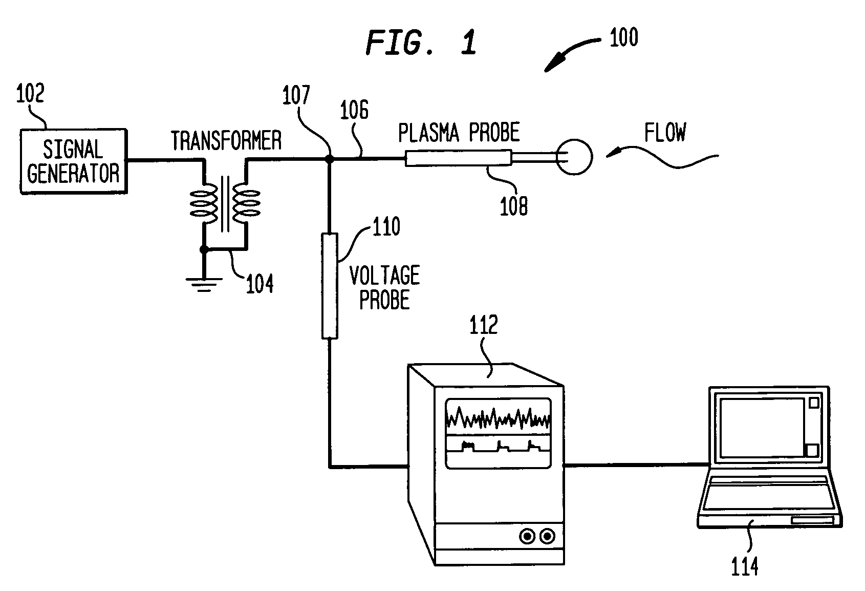
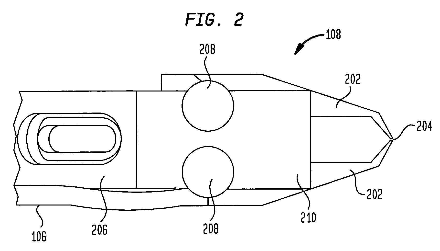
[0025]Embodiments of the present invention are generally directed to an AC driven, plasma anemometer for measuring flows at hypersonic Mach numbers. Such an anemometer uses a plasma discharge formed between two encapsulated electrodes as the primary sensing element. The plasma discharge is preferably driven by an Alternating Current (AC) power source, such as a low power (e.g., less than 5 Watt) AC source. Certain embodiments of the plasma anemometer include one or more of the following advantages: it requires no frequency compensation up to its AC carrier frequency, has an amplitude-modulated output that has excellent common-mode rejection with a signal-to-noise ratio that is improved over the output generated by hot-wire devices, does not include a sensor element that could easily break, it may have a small spatial volume, and is insensitive to temperature variations making it easier to calibrate than thermal-based sensors, and it may be operated across a myriad of different press...


PUM


Abstract

Methods and systems are described for a system for obtaining information regarding a flow. These methods and systems comprise a signal generator configured to generate an alternating current signal at a carrier frequency and a transformer arranged to receive the generated signal, wherein the transformer and carrier frequency are selected so that the generated signal resonates at the carrier frequency. The alternating signal is then used to cause plasma to form across a gap between two electrodes, wherein the voltage drop across the gap is directly proportional to the flow's velocity. This voltage may then be measured to determine the flow velocity.

Description

CROSS-REFERENCE TO RELATED APPLICATIONS[0001]This application claims priority from U.S. Provisional Application No. 60 / 610,951, filed Sep. 20, 2004, entitled “AC Plasma Anemometer for Hypersonic Mach Number Experiments,” now expired and which is hereby incorporated by reference herein.GOVERNMENT INTEREST STATEMENT[0002]The United States Government owns rights in the present invention as research relevant to the development of the invention was supported by United States federal funds from the Air Force Office of Scientific Research, Contract / Grant Number F49620-03-C-0055.BACKGROUND[0003]1. Field of the Invention[0004]The present invention relates generally to measurement systems, and more particularly, to methods and systems for a plasma anemometer and methods for using same.[0005]2. Related Art[0006]In recent years there has been a renewed interest in obtaining measurements in high-speed, high enthalpy flows where high-bandwidth sensitivity to mass-flux is desirable. The objectives...

Claims


Application Information

Patent Timeline
Patent Type & Authority Patents(United States)
IPC IPC(8): G01F1/58G01F1/00G01F1/05G01F1/20G01F1/56G01F1/60
CPCG01F1/64G01F1/72G01P5/08G01P13/025
Inventor MATLIS, ERICCORKE, THOMASGOGINENI, SIVARAM
Owner UNIV OF NOTRE DAME DU LAC
Why Eureka
Try Eureka