Portable electric cutting apparatus
a cutting machine and electric cutting technology, applied in the direction of portable power-driven tools, metal sawing accessories, manufacturing tools, etc., can solve the problems of reducing workability and reducing the strength of the base, and achieve the effect of high rectilinear propagation property, easy and precise cutting
- Summary
- Abstract
- Description
- Claims
- Application Information
AI Technical Summary
Benefits of technology
Problems solved by technology
Method used
Image
Examples
first embodiment
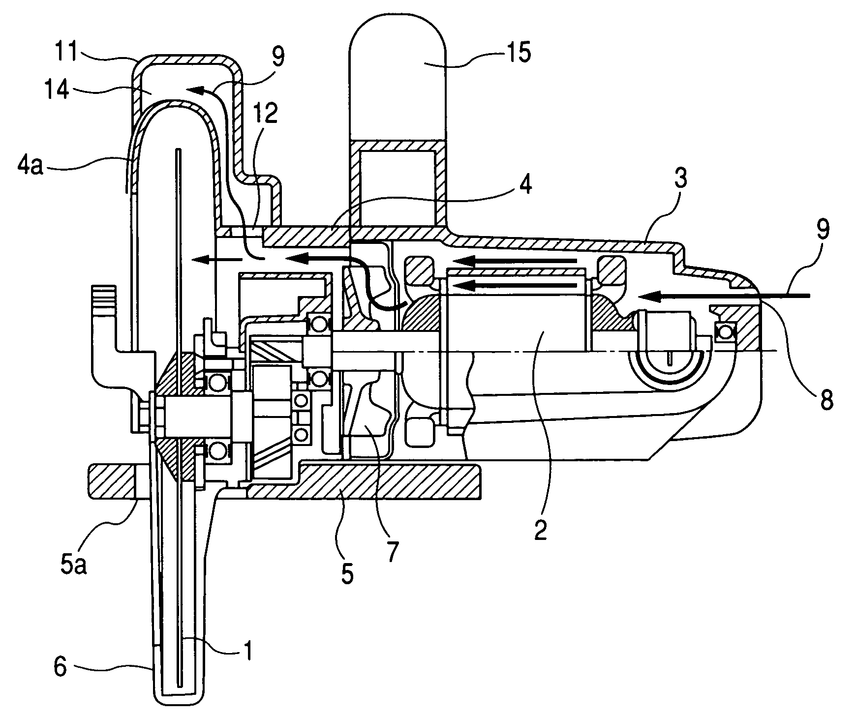
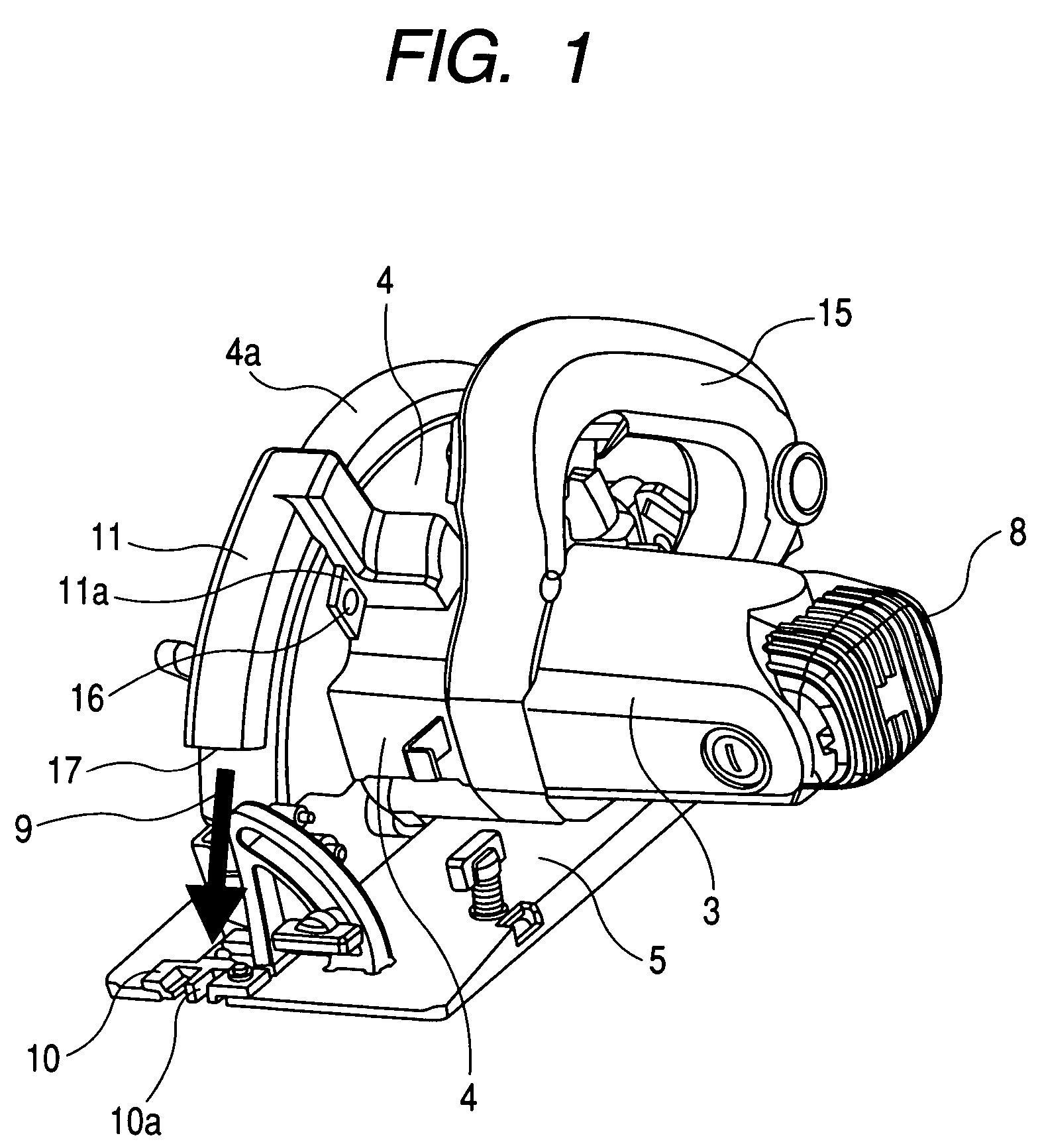
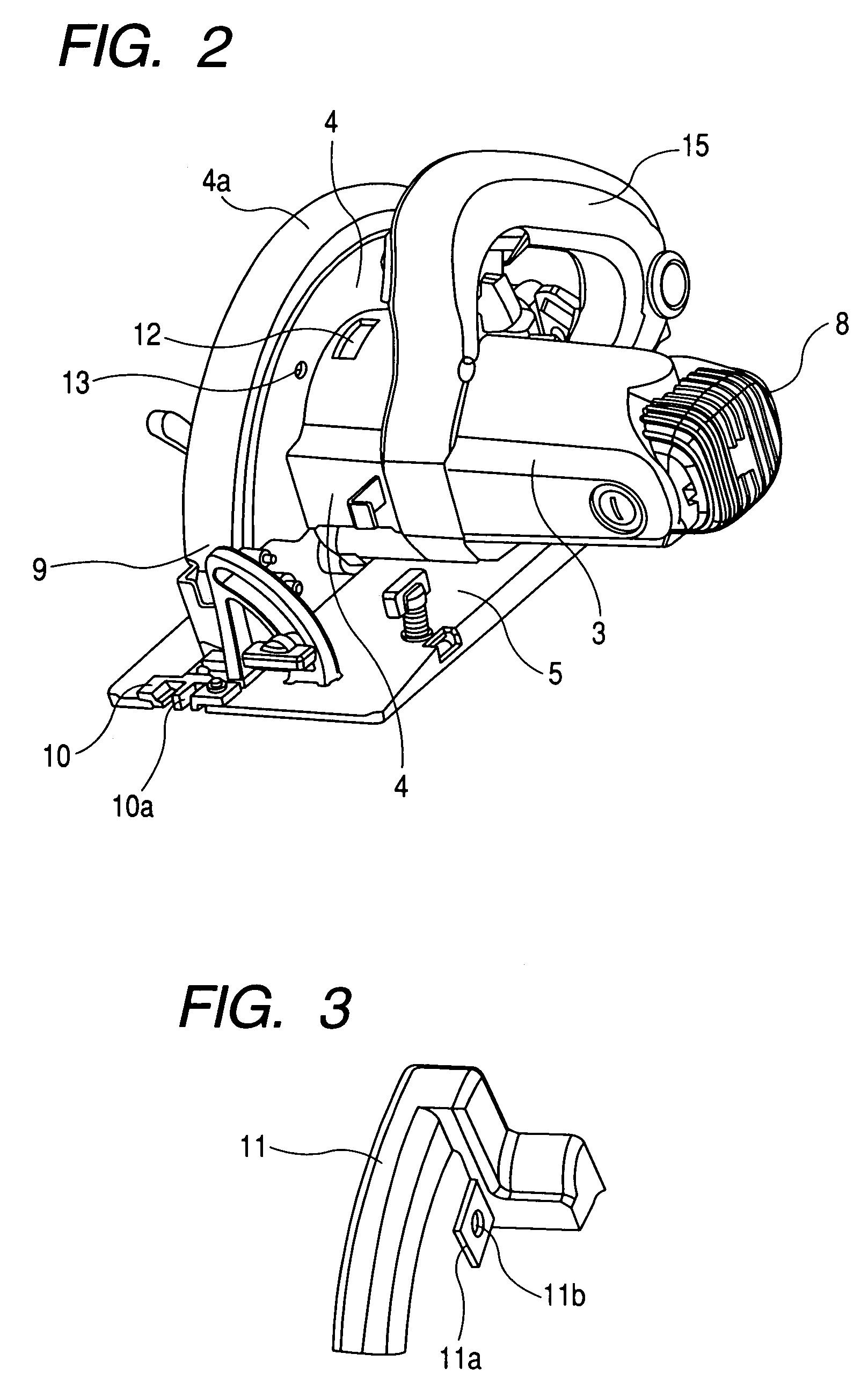
[0046]FIG. 1 is a perspective view of a portable circular saw according to a first embodiment of the invention, FIG. 2 is a perspective view to show a state in which a cover member of the portable circular saw is removed, FIG. 3 is a top perspective view of the cover member, FIG. 4 is a bottom perspective view of the cover member, FIG. 5 is a broken side view of the portable circular saw, FIG. 6 is a front perspective view of the cover member of the portable circular saw with parts partially broken away, and FIG. 7 is a bottom perspective view of the portable circular saw.
[0047]The portable circular saw according to the embodiment includes a saw blade 1, an electric motor 2 for rotating the saw blade 1, a motor housing 3 for housing the electric motor 2, a handle 15 projecting from the motor housing 3, a saw cover 4 for holding the saw blade 1 for rotation, and a base 5 placed below the motor housing 3 and the saw cover 4 and having an opening 5a for allowing the saw blade 1 to proj...
second embodiment
[0071]A second embodiment of the invention will be discussed with FIGS. 8 to 10.
[0072]FIG. 8 is a side view of a cover member of a portable circular saw with parts partially broken away according to the second embodiment of the invention, FIG. 9 is a broken side view of the portable circular saw, and FIG. 10 is a bottom view of the portable circular saw. Parts identical with those previously described with reference to FIGS. 1 to 7 are denoted by the same reference numerals in FIGS. 8 to 10 and will not be discussed again.
[0073]The portable circular saw according to the embodiment is characterized in that a laser oscillator 18 for emitting laser light L for guiding cutting toward the front side of a cut material in the cutting direction thereof is placed in a discharge passage 14 in a cover member 11, as shown in FIGS. 8 and 10, and other components are the same as those of the portable circular saw according to the first embodiment.
[0074]Since the laser light L emitted from the las...
third embodiment
[0079]Next a third embodiment of the invention will be discussed with FIG. 11. FIG. 11 is a sectional side view of a jig saw according to the third embodiment of the invention.
[0080]The embodiment is provided by applying the invention to a jig saw. To begin with, the basic configuration and function of the jig saw will be discussed below:
[0081]An electric motor 32 as a drive source is housed as transversely mounted in a housing 31 of a jig saw shown in the figure, a pinion 34 is placed at one end of an output shaft (motor shaft) 33 of the electric motor 32 in one piece, and a fan 35 is attached onto the output shaft inside the pinion 34.
[0082]A shaft 36 is placed above and in parallel with the output shaft 33 of the electric motor 32 in the housing 31 and a gear 37 is supported on the shaft 36 for rotation and meshes with the pinion 34 formed at the end of the output shaft 33. A pin 38 eccentric with respect to the shaft 36 is attached to the gear 37 and engages a sleeve guide 39.
[0...
PUM
| Property | Measurement | Unit |
|---|---|---|
| cylindrical shape | aaaaa | aaaaa |
| length | aaaaa | aaaaa |
| shape | aaaaa | aaaaa |
Abstract
Description
Claims
Application Information
 - R&D
- Intellectual Property
- Life Sciences
- Materials
- Tech Scout
- Unparalleled Data Quality
- Higher Quality Content
- 60% Fewer Hallucinations
Browse by: Latest US Patents, China's latest patents, Technical Efficacy Thesaurus, Application Domain, Technology Topic, Popular Technical Reports.
© 2025 PatSnap. All rights reserved.Legal|Privacy policy|Modern Slavery Act Transparency Statement|Sitemap|About US| Contact US: help@patsnap.com


