
Bulldozer

a bulldozer and lateral width technology, applied in the field of bulldozers, can solve the problems of reduced workability, limited large so as to suppress the increase of the longitudinal length and lateral width of the engine compartment, prevent the deterioration of workability, and suppress the height of the upper surface of the engine cover.

Active Publication Date: 2016-07-19
KOMATSU LTD
View PDF19 Cites 7 Cited by
  • Summary
  • Abstract
  • Description
  • Claims
  • Application Information

AI Technical Summary

Benefits of technology

The present invention provides a bulldozer with two or more exhaust treatment devices placed at the front of the engine. By arranging the devices in this way, the engine compartment remains compact, allowing for better visibility and workability of the blade. Additionally, the patent text describes a design that minimizes the width of the engine compartment, ensuring the operator has unobstructed visibility. The technical effect of this invention is to improve the performance and workability of the bulldozer by optimizing the arrangement and placement of exhaust treatment devices in the engine compartment.

Problems solved by technology

When the upper surface of the engine cover is raised, then the region visible to the operator on the upper portion of the blade of the working implement becomes restricted, so that the workability is reduced.
Moreover, when these two or more exhaust treatment devices are disposed at the side of the engine, then the lateral width of the engine compartment becomes large.
Therefore, the lateral width of the engine compartment is limited to being within such predetermined width.
Accordingly, when a diesel particular filter device and a selective catalytic reduction device are both disposed at the side of the engine, then it becomes difficult to limit the lateral width of the engine compartment to being within the predetermined dimension.
Furthermore, when the lateral width of the engine compartment becomes large, then the regions visible to the operator at the side portions of the blade of the working implement become restricted, and the workability is reduced.
In this case, the gap between the blade and the barycenter of the vehicle body becomes greater, so that the force transmitted to the blade is dissipated, and it becomes difficult to maintain digging force for the blade.

Method used


Image

  • Bulldozer
  • Bulldozer
  • Bulldozer

Examples


Embodiment Construction

Overall Structure

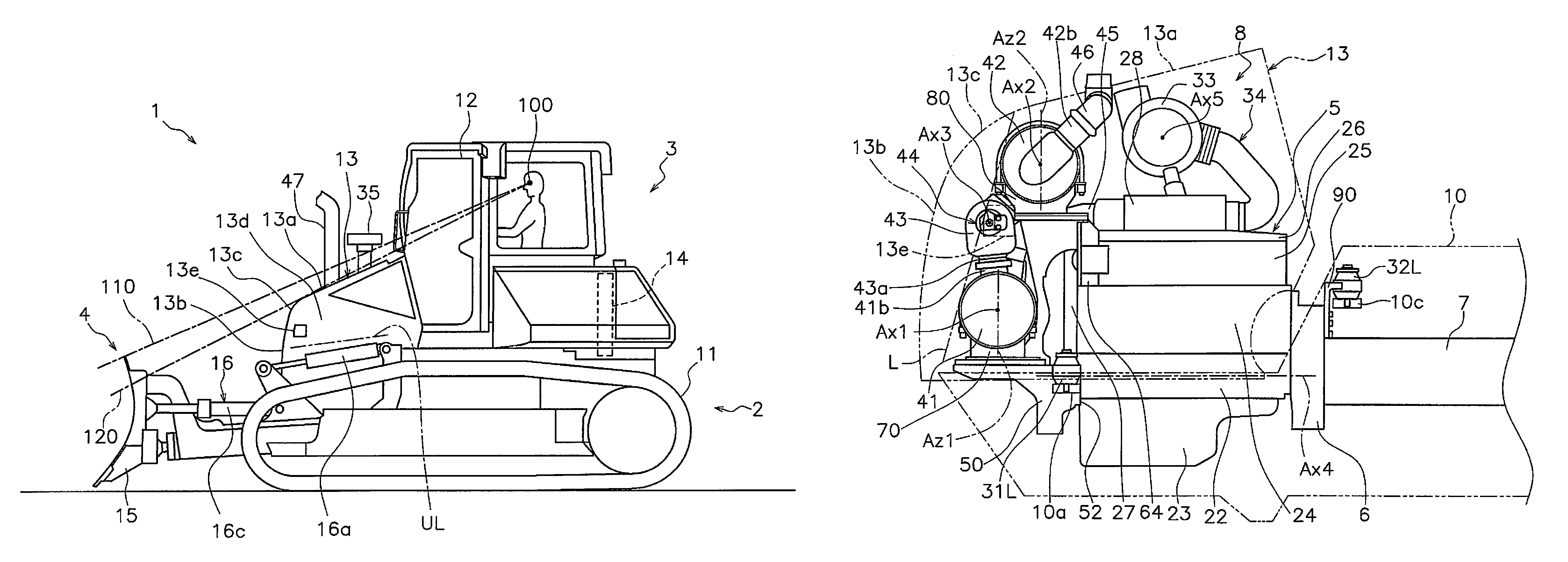
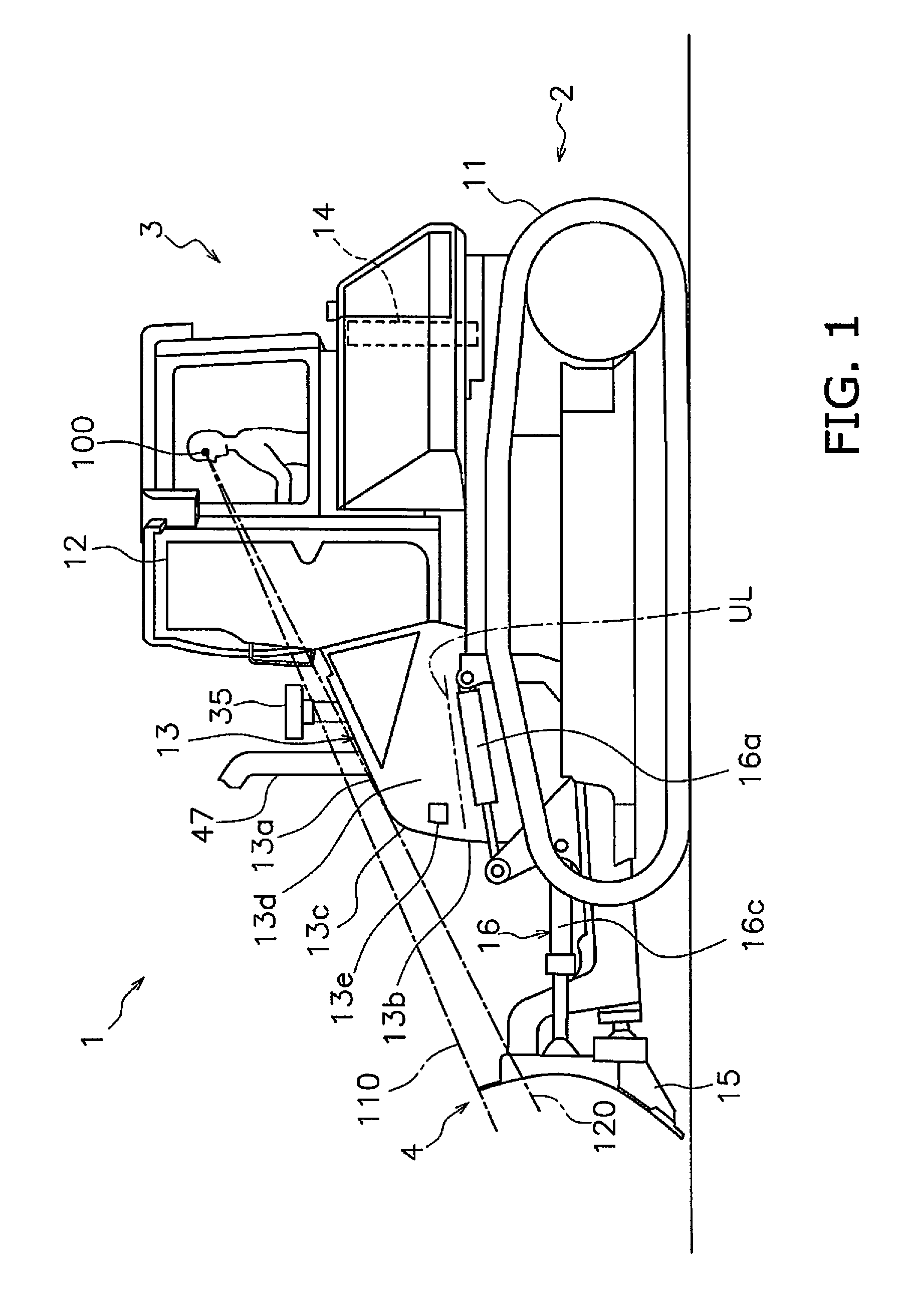
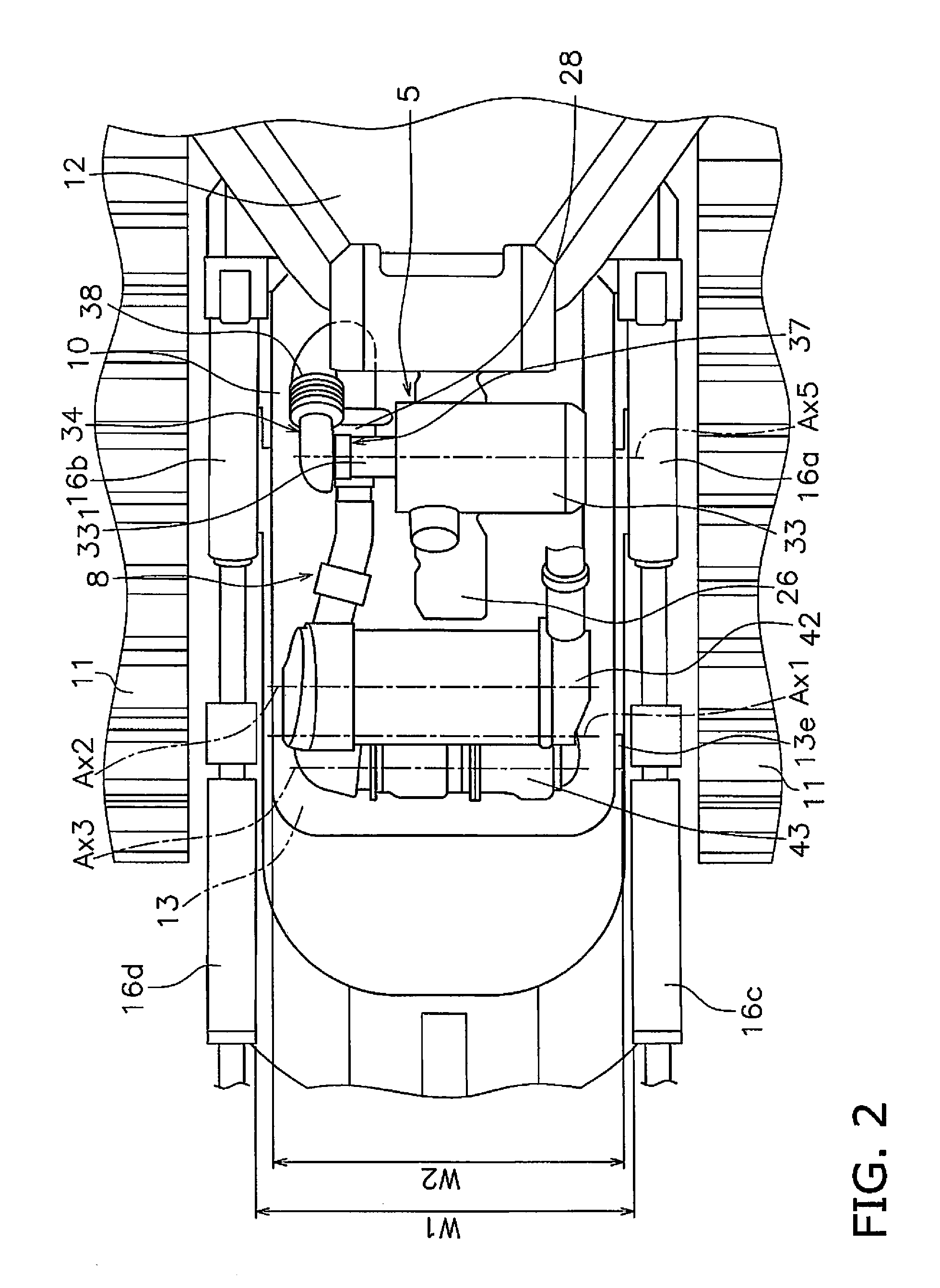
[0029]A left side view of a bulldozer 1 according to an exemplary embodiment of the present invention is shown in FIG. 1. A top view illustrating a part of the bulldozer according to this exemplary embodiment of the present invention is shown in FIG. 2. In FIG. 2, an engine compartment 8 is shown in a state in which an engine cover 13, which will be described hereinafter, has been removed. It should be understood that, in the following explanation, the “front / rear direction” means the front / rear direction of the bulldozer 1. To put it in other words, the front / rear direction means the front / rear direction as seen by an operator sitting in a cab (an operator compartment) 12. Moreover, the left / right direction means the left / right direction as seen by an operator sitting in the cab (the operator compartment). Furthermore, the lateral direction means the direction lateral to the vehicle, i.e. to the bulldozer 1; in other words, it means either one of the left direction...


PUM


Abstract

A first exhaust treatment device, a second exhaust treatment device, and a relay connection pipe are disposed in front of an engine of a bulldozer. A relay connection pipe connects the first and second exhaust treatment devices. An injector assembly is attached to the relay connection pipe. The first exhaust treatment device, the relay connection pipe, and the second exhaust treatment device are arranged in sequence such that longitudinal directions thereof extend along the vehicle lateral direction. An attachment surface for the injector on the relay connection pipe is provided on an offset portion of the relay connection pipe at a connection portion between the first exhaust treatment device and the relay connection pipe. The distance between the injector assembly and a first side surface of the engine cover closest to the injector assembly is substantially equal to the distance between the first side surface and the first exhaust treatment device.

Description

CROSS-REFERENCE TO RELATED APPLICATIONS[0001]This application is a U.S. National stage application of International Application No. PCT / JP2013 / 062476, filed on Apr. 26, 2013.BACKGROUND[0002]1. Field of the Invention[0003]The present invention relates to a bulldozer, which is one type of work vehicle.[0004]2. Background Information[0005]In Japanese Laid-Open Patent Publication 2005-113674, a bulldozer is disclosed in which the upper surface of the engine cover is tilted forward and downward (refer to Patent Japanese Laid-Open Patent Publication 2005-113674). With the bulldozer the workability is enhanced, since the operator is able visually to check the upper portion of the blade, i.e. of the working implement.[0006]On the other hand, from the standpoint of protection of the natural environment, a work vehicle, such as a bulldozer, needs purifying of the exhaust (refer to the specification of US Laid-Open Patent Publication 2011 / 0079003A1). Therefore, it is nowadays practiced to moun...

Claims


Application Information

Patent Timeline
Patent Type & Authority Patents(United States)
IPC IPC(8): B60K13/04F01N3/20E02F3/815F01N13/00F01N13/18E02F9/20E02F3/76E02F9/08
CPCE02F9/20B60K13/04E02F3/7631E02F3/815E02F9/0866F01N3/206F01N13/009F01N13/18F01N13/1805B60Y2200/411F01N2340/04F01N2590/08F01N2610/00F01N3/106F01N3/2066F01N3/021F01N2610/02F01N2610/1453E02F9/0891Y02A50/20Y02T10/12
Inventor SAKAI, KIYOTAKA
Owner KOMATSU LTD
Learn More