Rolling member, rolling bearing and process for manufacturing rolling member

a technology of rolling bearings and rolling parts, which is applied in the direction of gearing, heat treatment equipment, furnaces, etc., can solve the problems of insufficient lubrication, reduced viscosity of lubricating oil, and deterioration of lubricating oil for the bearing, so as to reduce workability and increase the manufacturing cost of steel.

Active Publication Date: 2013-09-17
NTN CORP
View PDF46 Cites 8 Cited by
  • Summary
  • Abstract
  • Description
  • Claims
  • Application Information

AI Technical Summary

Benefits of technology

[0077]As obvious from the above description, a rolling member and a rolling bearing having a long life also in a high-temperature environment or an environment infiltrated with water, and a process for manufacturing the rolling member can be provided according to the inventive rolling member, the inventive rolling bearing and the inventive process for manufacturing the rolling member, while suppressing the contents of alloying elements causing reduction of the workability or increase of the manufacturing cost in steel constituting the rolling member.

Problems solved by technology

For example, a calendar roll support bearing of a papermaking machine or a roll support bearing of iron and steel rolling equipment is used in a high-temperature environment which is a temperature environment higher than ordinary temperature (room temperature), and hence lubricating oil for the bearing may be deteriorated or the viscosity of the lubricating oil may be reduced, to result in insufficient lubrication.
Further, abrasion or a rust pit may be caused on a rolling surface which is a surface coming into contact with another rolling member on the surface of the rolling member due to water vapor in the atmosphere or cooling water, and the rolling member may be flaked in an early stage with the abrasion or the rust pit serving as a starting point.
In other words, an oil film is broken due to insufficient lubrication and the rolling members come into metallic contact with each other on the rolling surfaces to cause surface damage (peeling or abrasion, for example), or the rolling surface is rusted due to water derived from the water vapor or the cooling water to cause surface damage from the rust serving as a starting point, to cause flaking in the rolling member in an early stage.
Further, such a phenomenon (flaking resulting from hydrogen embrittlement) that hydrogen generated by decomposition of water infiltrating the bearing or hydrogen generated by decomposition of the lubricating oil with catalysts of nascent surfaces of metal appearing due to metallic contact between the rolling elements infiltrates the rolling members to cause flaking on the rolling surfaces in a short period is also problematic.

Method used


Image

  • Rolling member, rolling bearing and process for manufacturing rolling member
  • Rolling member, rolling bearing and process for manufacturing rolling member
  • Rolling member, rolling bearing and process for manufacturing rolling member

Examples


first embodiment

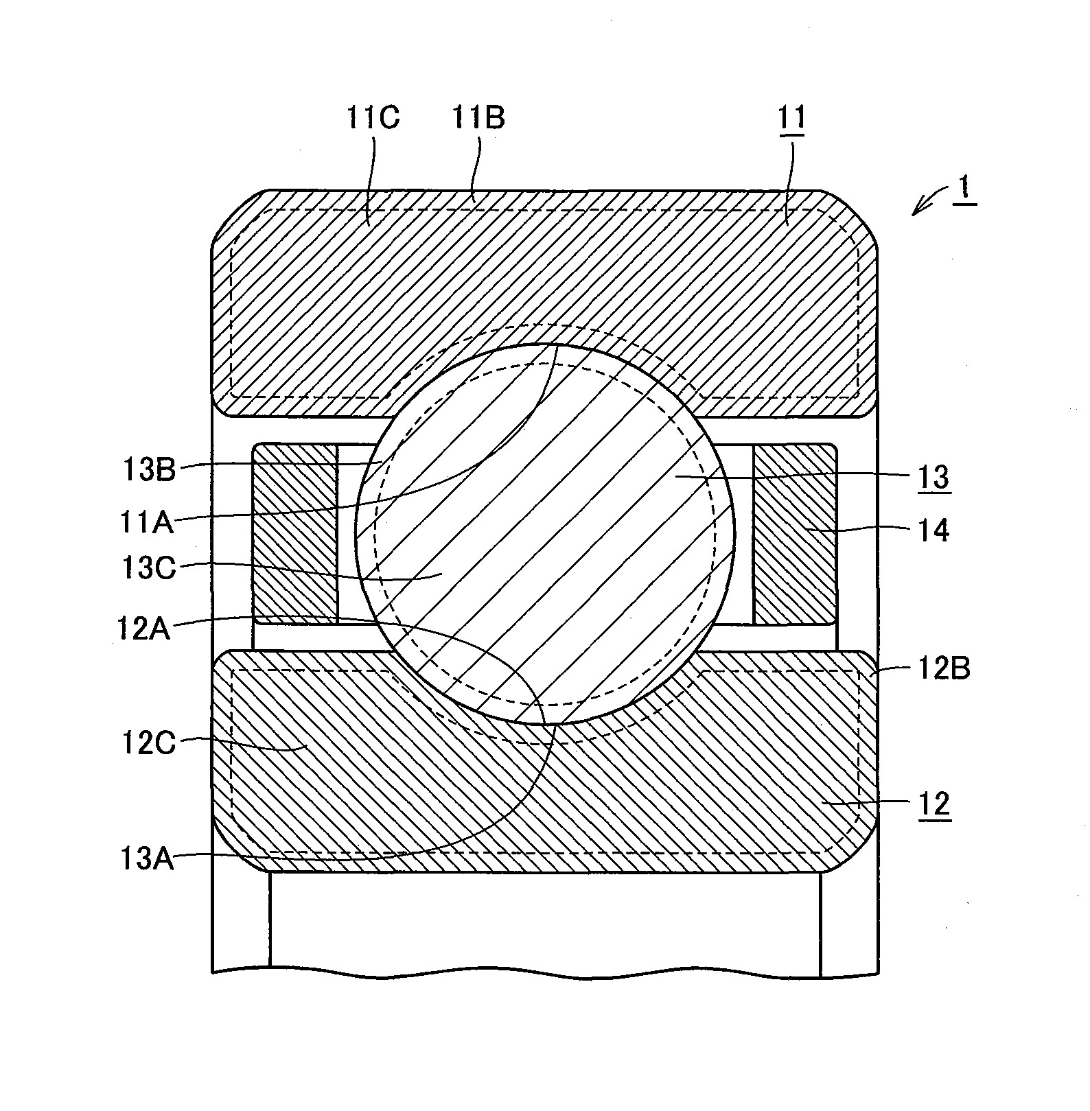
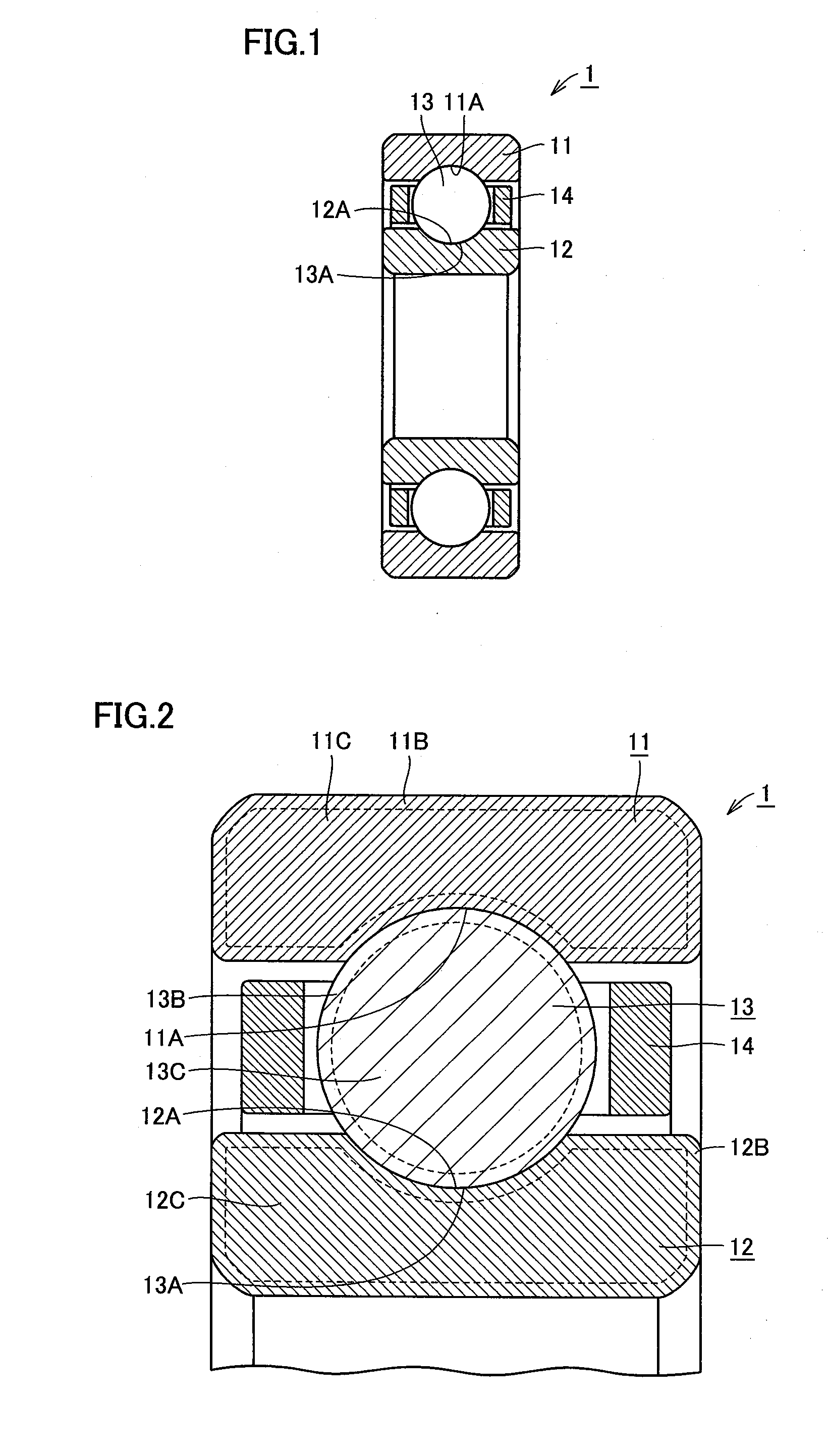
[0119]First, the structures of a deep-groove ball bearing as a rolling bearing and bearing races and balls as rolling members according to a first embodiment of the present invention are described with reference to FIGS. 1 and 2.

[0120]Referring to FIG. 1, a deep-groove ball bearing 1 according to the first embodiment includes an annular outer race 11, an annular inner race 12 arranged inside outer race 11 and a plurality of balls 13 as rolling elements arranged between outer race 11 and inner race 12 and held in an annular cage 14. An outer race rolling surface 11A is formed on the inner peripheral surface of outer race 11, while an inner race rolling surface 12A is formed on the outer peripheral surface of inner race 12. Outer race 11 and inner race 12 are so arranged that inner race rolling surface 12A and outer race rolling surface 11A are opposed to each other. Plurality of balls 13 are in contact with inner race rolling surface 12A and outer race rolling surface 11A and arrange...

second embodiment

[0150]Rolling members and a rolling bearing according to a second embodiment are now described.

[0151]Referring to FIG. 6, a self-aligning roller bearing 2 basically has a structure similar to that of deep-groove ball bearing 1 described with reference to FIGS. 1 and 2. In shapes of bearing races and rolling elements, however, self-aligning roller bearing 2 according to the second embodiment is different from deep-groove ball bearing 1 according to the first embodiment.

[0152]In self-aligning roller bearing 2, the inner peripheral surface of an outer race 21 is in the form of a spherical surface whose center aligns with the bearing center, two rows of raceway grooves are formed on the outer peripheral surface of an inner race 22, and two rows of barrel-shaped rollers 23 held by a cage 24 are provided between outer race 21 and inner race 22. Alignability against inclination of a shaft or the like is obtained due to the two rows of barrel-shaped rollers 23. In rollers 23, the overall ou...

third embodiment

[0156]Rolling members and a rolling bearing according to a third embodiment are now described.

[0157]Referring to FIG. 7, a quadruple conical roller bearing 3 basically has a structure similar to that of deep-groove ball bearing 1 described with reference to FIGS. 1 and 2. In shapes of bearing races and rolling elements, however, quadruple conical roller bearing 3 according to the third embodiment is different from deep-groove ball bearing 1 according to the first embodiment.

[0158]In other words, quadruple conical roller bearing 3 includes four annular outer races 31, two annular inner races 32 arranged inside outer races 31, and a plurality of conical rollers 33 arranged between outer races 31 and inner races 32. Four outer races 31 and two inner races 32 are so arranged that the outer peripheral surfaces of inner races 32 are opposed to the inner peripheral surfaces of two outer races 31 respectively. Further, plurality of rollers 33 are in contact with outer race rolling surfaces ...


PUM

PropertyMeasurementUnit
grain sizeaaaaaaaaaa
lengthaaaaaaaaaa
distanceaaaaaaaaaa

Abstract

The invention provides a deep groove ball bearing which exhibits a long life even in a high-temperature environment or an environment involving the penetration of water in spite of its low alloying element content. The outer race, inner race and ball constituting the bearing are made of a steel which contains 0.3 to 0.4% of carbon, 0.3 to 0.7% of silicon, 0.3 to 0.8% of manganese, 0.5 to 1.2% of nickel, 1.6 to 2.5% of chromium, 0.1 to 0.7% of molybdenum and 0.2 to 0.4 of vanadium with the balance consisting of iron and impurities and in a total content of silicon and manganese of 1.0% or below, a total content of nickel and chromium of 2.3% or above and a total content of chromium, molybdenum and vanadium of 3.0% or below. Surface hardened layers are formed in the outer race, inner race and ball respectively and the surface hardened layers exhibit hardness of 725 to 800 HV, while the maximum particle size of carbides dispersed in the surface hardened layers is 10 μm or below and the area ratio thereof is 7 to 25%. Further, the inner parts exhibit hardness of 450 to 650 HV.

Description

RELATED APPLICATIONS[0001]This application is the U.S. National Phase under 35 U.S.C. §371 of International Application No. PCT / JP2008 / 058634, filed on May 9, 2008, which in turn claims the benefit of Japanese Application Nos. 2007-131960, filed on May 17, 2007; 2007-153136, filed on Jun. 8, 2007; 2007-153137, filed on Jun. 8, 2007; 2007-156703, filed on Jun. 13, 2007 and 2007-162877, filed on Jun. 20, 2007, the disclosures of which Applications are incorporated by reference herein.TECHNICAL FIELD[0002]The present invention relates to a rolling member, a rolling bearing and a process for manufacturing the rolling member, and more specifically, it relates to a rolling member and a rolling bearing usable also in a severe environment such as a high-temperature environment or an environment infiltrated with water, and a process for manufacturing the rolling member.BACKGROUND ART[0003]In recent years, a rolling member such as a bearing component constituting a rolling bearing has increas...

Claims


Application Information

Patent Timeline
Patent Type & Authority Patents(United States)
IPC IPC(8): F16C33/34C23C8/32C23C8/22C22C38/44C22C38/46
CPCC21D1/06C21D9/40C22C38/02C22C38/04C22C38/44C22C38/46C23C8/22C23C8/32C23C8/80F16C33/62F16C33/64C21D1/18F16H41/24F16H3/0915F16H3/16F16H9/18
Inventor MAEDA, KIKUO
Owner NTN CORP
Why Eureka
Try Eureka