Hand grenade simulating device

a technology of hand grenade and simulating device, which is applied in the direction of hand grenade, ammunition fuze, toys, etc., can solve the problems of difficult and expensive fabrication, and achieve the effects of low cost, easy fabrication, and simple construction

Inactive Publication Date: 2007-10-02
HSIEH CHI PENG
View PDF5 Cites 13 Cited by
  • Summary
  • Abstract
  • Description
  • Claims
  • Application Information

AI Technical Summary

Benefits of technology

[0005]The object of the present invention is to provide a hand grenade simulating device which has a simple construction and which is easy to fabricate at a relatively low cost.

Problems solved by technology

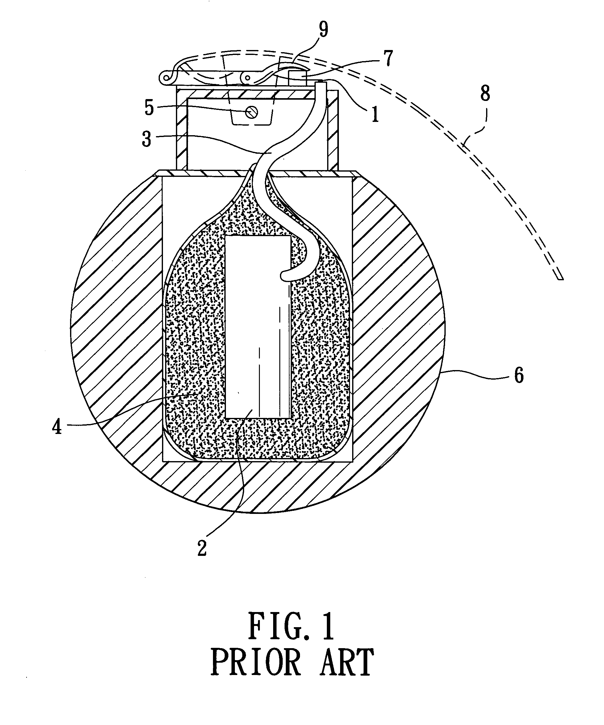
However, the ignition member 1 has a complicated structure and thus is difficult and expensive to fabricate.

Method used


Image

  • Hand grenade simulating device
  • Hand grenade simulating device
  • Hand grenade simulating device

Examples


Embodiment Construction

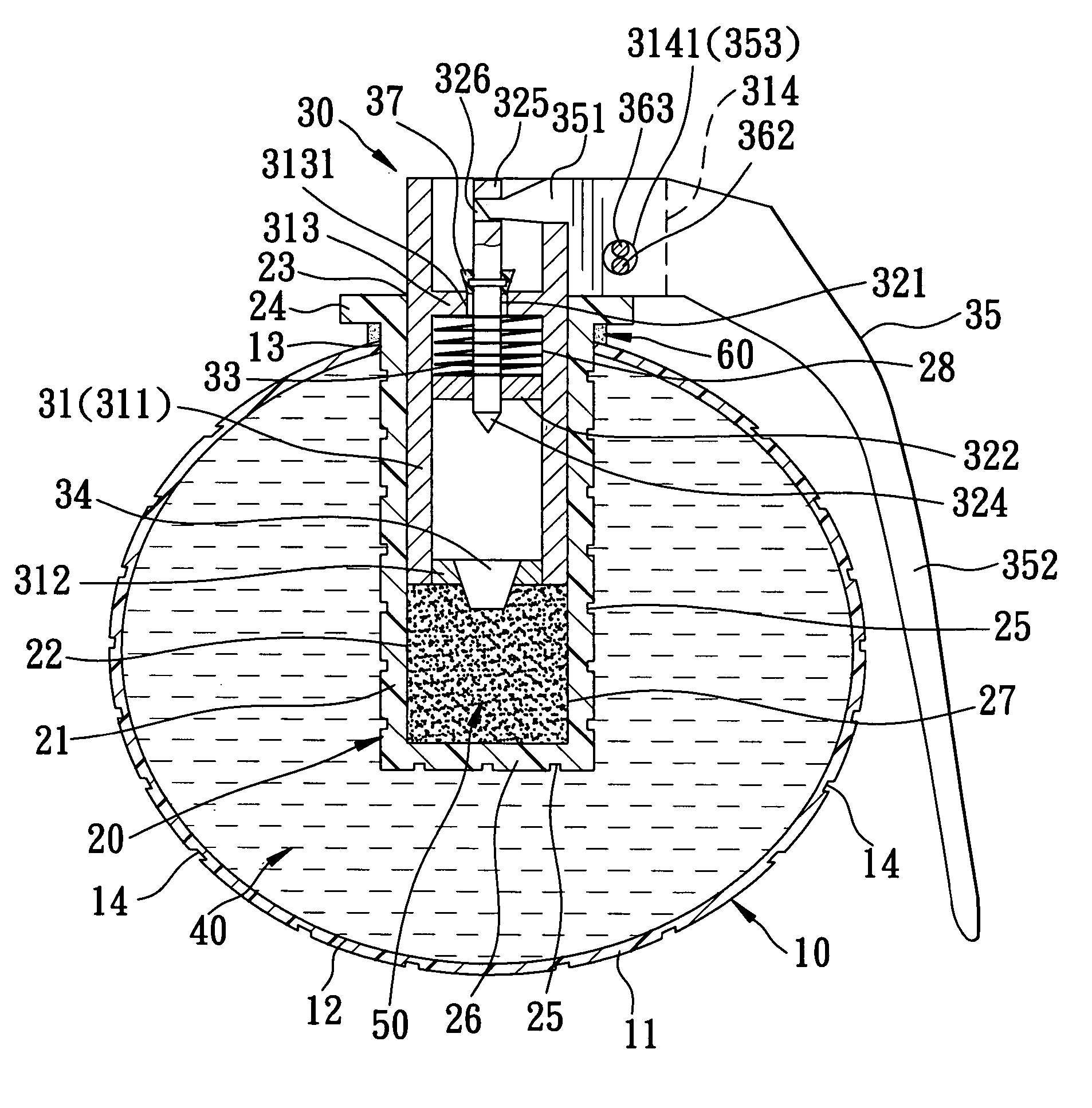
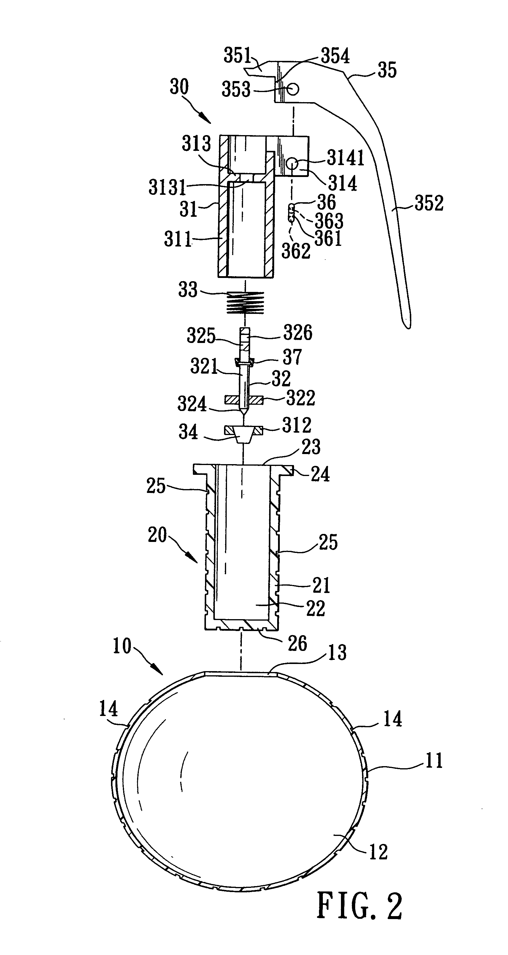
[0014]Referring to FIGS. 2 to 4, the preferred embodiment of a hand grenade simulating device according to the present invention is shown to comprise a first shell 10, a second shell 20, an ignition unit 30, a marking filler 40, a colored powder 50, and a seal member 60.

[0015]The first shell 10 is made from a soft plastic material, such as PE, and has a spherical wall 11 defining a first accommodation space 12 therein and a first access opening 13 for accessing the first accommodation space 12. A plurality of weakening indents 14 are formed in the spherical wall 11 so as to render the first shell 10 prone to rupture.

[0016]The second shell 20 is received in the first accommodation space 12 by extending through the first access opening 13, and includes a bottom wall 26 with a periphery, and a surrounding wall 21 integrally formed from the periphery of the bottom wall 26 and extending from the periphery of the bottom wall 26 in a longitudinal direction to define a second accommodation ...


PUM


Abstract

A hand grenade simulating device includes a first shell filled with a marking filler, a second shell disposed in the first shell for receiving a percussion-triggered charge, a striking member which is remote from the charge in a ready position and which is movable to strike the charge by a biasing force of a biasing member to initiate detonation for exploding the first and second shells and scattering the marking filler, a releasably retaining member which is disposed to hold the striking member in the ready position and which is manually releasable, and a delay member disposed to generate a kinetic frictional force between the striking member and the second shell such that the striking member is dragged by the frictional force against the biasing force of the biasing member when the releasably retained member is released.

Description

BACKGROUND OF THE INVENTION[0001]1. Field of the Invention[0002]This invention relates to a hand grenade simulating device, more particularly to a hand grenade simulating device which simulates a hand grenade to be used in military training or recreational war games.[0003]2. Description of the Related Art[0004]Referring to FIG. 1, a conventional simulated hand grenade used in military training or recreational war games, such as that disclosed in U.S. Pat. No. 4,932,329, includes a frangible outer shell 6, a small charge 2 within the shell 6, a fuse 3 for delaying detonation of the charge 2, an ignition member 1 for activating the fuse 3, and a dye powder 4 is filled within the shell 6. The fuse 3 is a lacquered igniter wire which burns to provide a delayed detonation of two to ten seconds after ignition. The ignition member 1 has a spring-loaded hammer 9 disposed to impact a primer cap 7 when released so as to explode the cap 7, thereby igniting an end of the igniter wire 3. The spr...

Claims


Application Information

Patent Timeline
Patent Type & Authority Patents(United States)
IPC IPC(8): F42B8/26F42C15/21
CPCF42B8/26
Inventor HSIEH, CHI-PENG
Owner HSIEH CHI PENG
Why Eureka
Try Eureka