
Method for engaging the starter pinion of a starter with the starter ring gear of an internal combustion engine during the running-down of the internal combustion engine

a technology of starter ring and starter pinion, which is applied in the direction of engine starters, machines/engines, power operated starters, etc., can solve the problems of multiple rotational directions of the engine, unavoidable starting noises, and affecting riding comfor

Inactive Publication Date: 2007-10-02
ROBERT BOSCH GMBH
View PDF6 Cites 96 Cited by
  • Summary
  • Abstract
  • Description
  • Claims
  • Application Information

AI Technical Summary

Benefits of technology

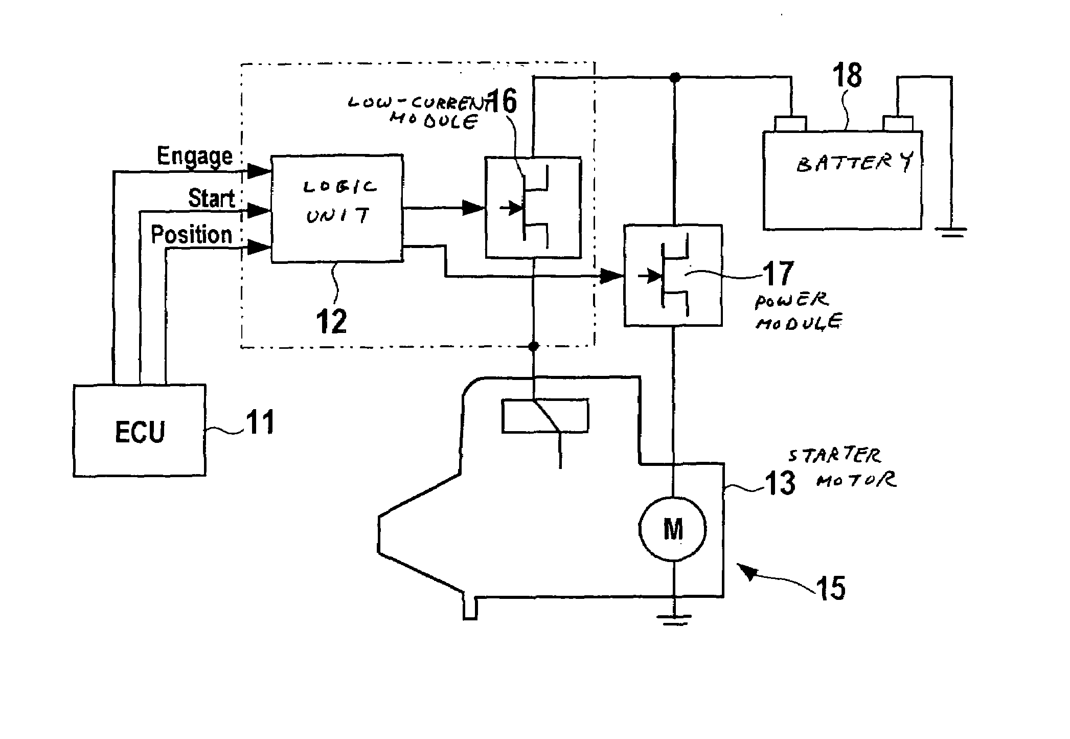
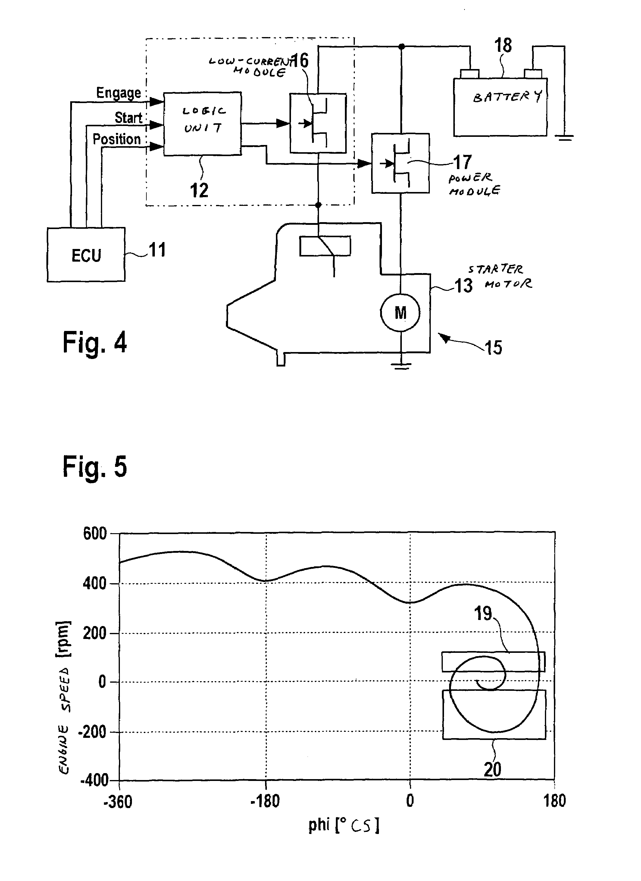
The present invention provides a method for engaging the starter of an internal combustion engine with the starter ring gear during the running-down of the engine. This is done by transmitting an engaging signal to the starter when the speed of the engine is within a certain range and the rotational direction of the crankshaft corresponds to the forward rotational direction. The method prevents stressing of parts and ensures that engagement does not occur when the engine is rotating backwards. The control unit for the starter includes a model of the running-down characteristics of the engine to determine the suitable time for engagement. This method advantageously takes into account the possible delay between the generation of the engaging signal and the actual engagement. The control unit for the starter also includes control means for engaging the starter pinion with the starter ring gear when the conditions are met.

Problems solved by technology

The restarting produces unavoidable starting noises, which affect riding comfort.
It is problematic that the rotational direction of the engine can change several times during the running-down phase of the engine.
This known, final oscillation of the engine during the running-down of the engine is disadvantageous for the engagement of the starter pinion with the starter ring gear, since it may result in engagement occurring during a reversing motion of the engine, which in turn results in a marked jerk of the engine.
This jerk stresses the mechanical parts and is perceived by the driver as uncomfortable.

Method used


Image

  • Method for engaging the starter pinion of a starter with the starter ring gear of an internal combustion engine during the running-down of the internal combustion engine
  • Method for engaging the starter pinion of a starter with the starter ring gear of an internal combustion engine during the running-down of the internal combustion engine
  • Method for engaging the starter pinion of a starter with the starter ring gear of an internal combustion engine during the running-down of the internal combustion engine

Examples


Embodiment Construction

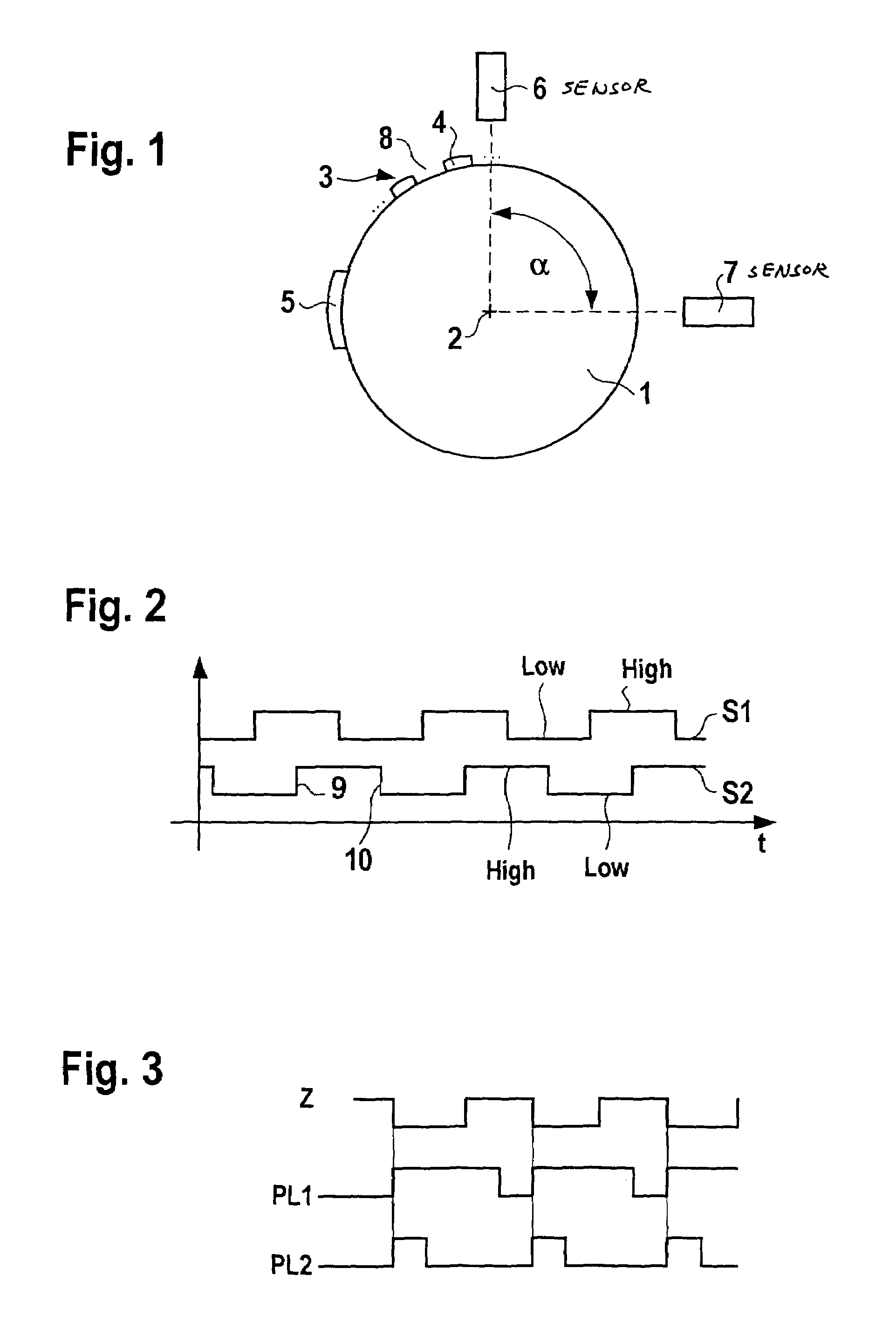
[0018]FIG. 1 shows a schematic illustration of a signal-generating disk 1 having two sensors assigned to the signal-generating disk. The signal-generating disk 1 is, for example, situated directly on a crankshaft or camshaft, or is indirectly connected to the camshaft with respect to the rotation, using gear elements. The signal-generating disk rotates about an axis 2. Markings 3 are situated at the circumference of signal-generating disk 1. The markings are made up, for example, of teeth 4, which are each positioned equidistantly over the circumference of the signal-generating disk. In each instance, tooth spaces 8 are situated between teeth 4. A further mark 5, e.g., in the form of a tooth 4 twice as wide, as shown here, or in the form of a greater tooth distance between two teeth 4 or the like, designates an identified neutral position of the crankshaft (zero marking). The teeth each run across an angle of approximately 3°, the tooth spaces run across an angle of 3°. Therefore, a...


PUM


Abstract

A method is provided for engaging a starter pinion of a starter with a starter ring gear of an internal combustion engine during the running-down of the internal combustion engine, which internal combustion engine has an arrangement for determining rotational speed and rotational direction of a crankshaft. The starter pinion is engaged with the starter ring gear when the following conditions are satisfied: a) the speed of the internal combustion engine is below a maximum speed and above a minimum speed; and b) the rotational direction corresponds to the forward rotational direction of the crank shaft.

Description

FIELD OF THE INVENTION[0001]The present invention relates to a method for engaging a starter pinion of a starter with a starter ring gear of an internal combustion engine during the running-down of the engine.BACKGROUND INFORMATION[0002]One method for reducing the fuel consumption of internal combustion engines, in particular vehicles, is start / stop operation, in which the vehicle engines are switched off, for instance, when stopped for a relatively long time in front of traffic lights. As soon as the driver wants to continue driving, the vehicle engine is restarted. The restarting produces unavoidable starting noises, which affect riding comfort. The starting noises are a consequence of, inter alia, the engagement of the starter pinion with the starter ring gear of the vehicle.[0003]In order to reduce the engaging noise and the starting time as well, it is known that the engagement for restarting the engine can be carried out not only after the engine is completely stopped, but rat...

Claims


Application Information

Patent Timeline
Patent Type & Authority Patents(United States)
IPC IPC(8): F02N11/00F02N15/02F02N99/00
CPCF02N11/0844F02N11/0855F02N15/04F02N2200/022F02N2250/04Y10T74/131F02N2300/2008Y02T10/48Y10T74/137Y10T74/13F02N2300/2006Y02T10/40
Inventor KASSNER, UWE
Owner ROBERT BOSCH GMBH
Learn More