
Music synthesis system

a music synthesis and system technology, applied in static storage, instruments, electrophonic musical instruments, etc., can solve the problems of heavy processing load of conventional music synthesis systems, large number of repeated calculations of pitch-shifting, and high storage cost, so as to maintain the quality of digital music output and reduce processing load

Active Publication Date: 2007-10-02
XUESHAN TECH INC
View PDF58 Cites 4 Cited by
  • Summary
  • Abstract
  • Description
  • Claims
  • Application Information

AI Technical Summary

Benefits of technology

[0010]The objective of the present invention is to provide a music synthesis system and method for performing memory management according to the importance of the data, so as to decrease the cost and processing load and maintain the quality of the digital music output.
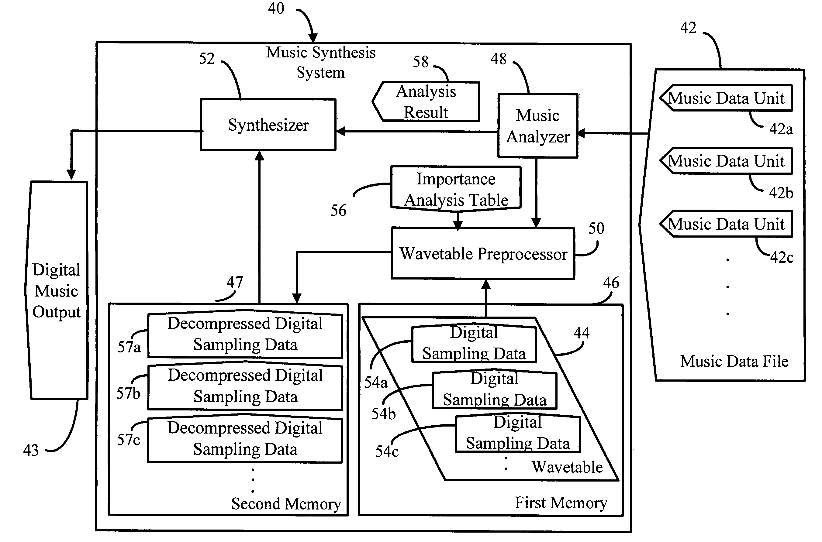
[0013]According to the embodiment, a music synthesis system and method for performing memory management according to the importance of a data is provided. The analysis result in the importance analysis table can be used to facilitate the limited-capacity of the memory in a more efficient way. Instead of storing all the received uncompressed music data files as performed in the prior arts, the inclusion of this table in the present music synthesis system generally allows only the storage of the digital sampling data with higher importance in the limited memory. If the memory capacity of the memory allows, the wavetable preprocessor can perform pitch-shifting to part of the digital sampling data and store those data in the memory, so as to share the processing load of the synthesizer and avoid performing the required calculations of pitch-shifting repeatedly. Therefore, the music synthesis system could decrease the cost and processing load while maintaining the quality of the digital music output.

Problems solved by technology

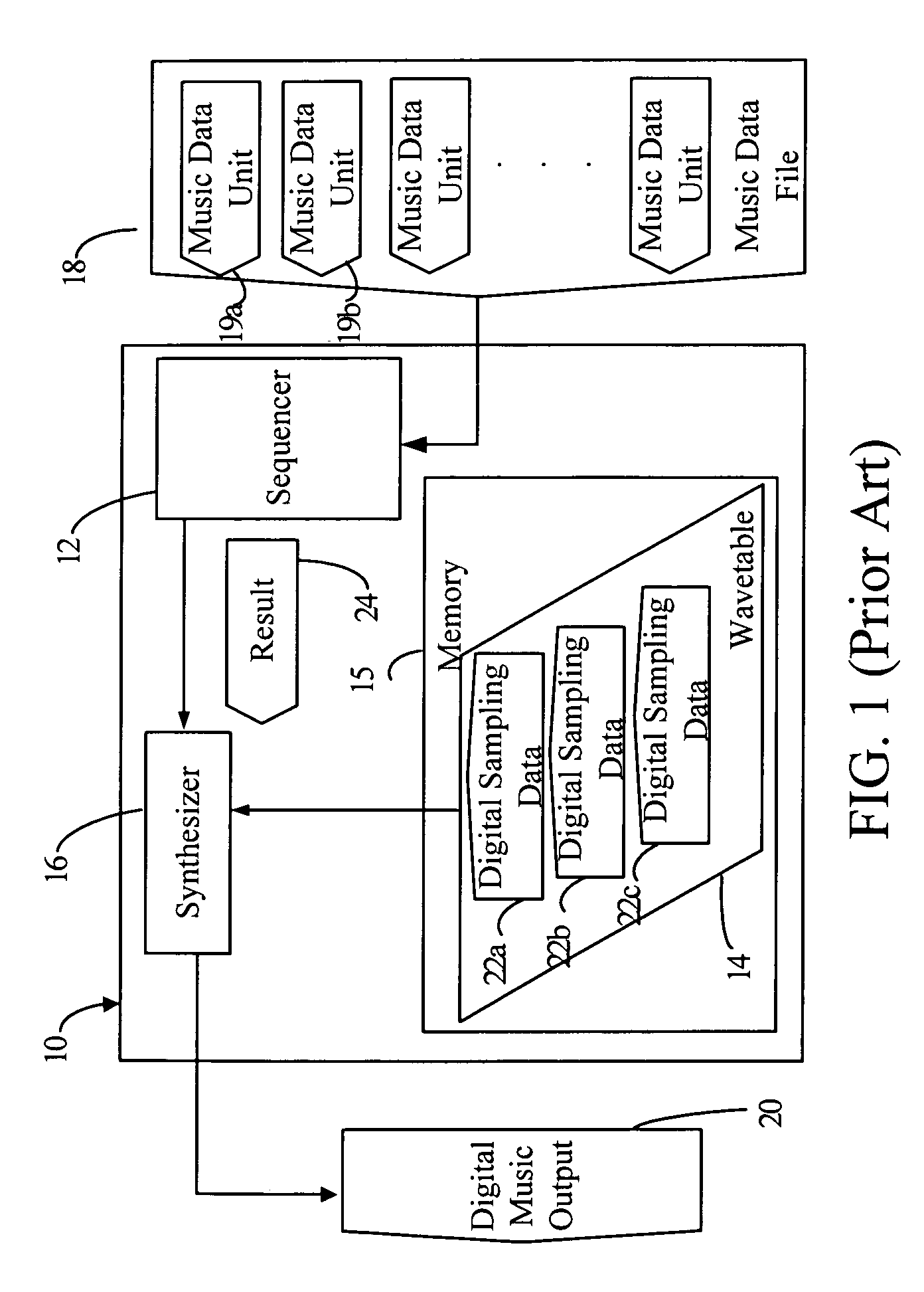
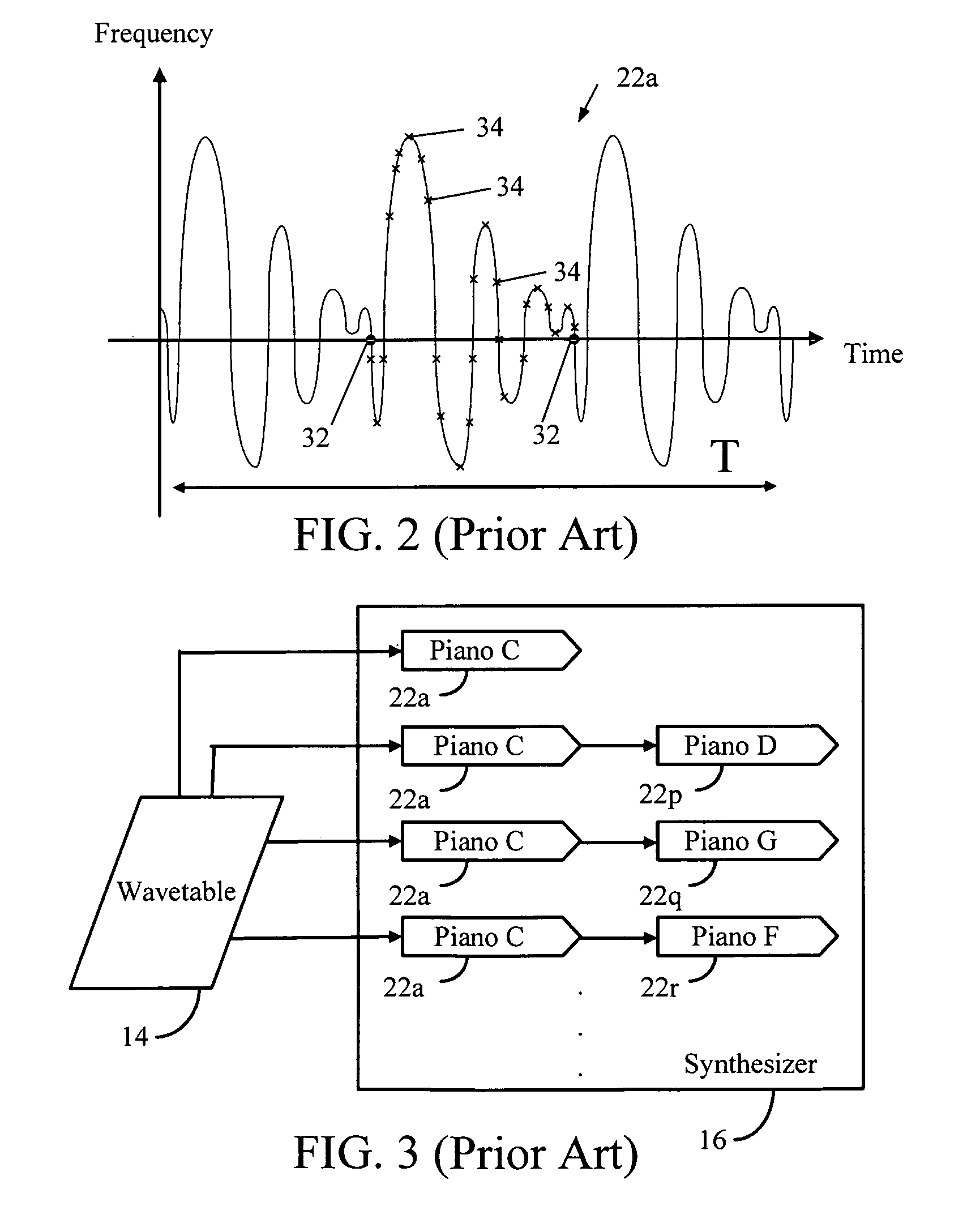
Therefore, a large number of repeated calculations of pitch-shifting could be a heavy processing load to conventional music synthesis system 10.
According to the above, conventional music synthesis system 10 has the disadvantages of high storing cost and high calculating cost.

Method used


Image

  • Music synthesis system
  • Music synthesis system
  • Music synthesis system

Examples


Embodiment Construction

[0020]Referring to FIG. 4, FIG. 4 is a schematic diagram of the music synthesis system 40 of the embodiment. The music synthesis system 40 is used for reading a music data file 42 and synthesizing a corresponding digital music output 43 according to commands specified in the music data file 42. The music synthesis system 40 comprises a wavetable 44, a first memory 46, a second memory 47, a music analyzer 48, a wavetable preprocessor 50, and a synthesizer 52. The digital music output 43 can be transmitted to a digital / analog converter (not shown) and a speaker (not shown) for converting the digital music output 43 into audible music or audio sounds.

[0021]The music data file 42 could be obtained by decoding a MIDI data stream. The music data file 42 comprises a plurality of music data units (42a, 42b, 42c, . . . ). A music data unit(42a, 42b or 42c) usually, but not limited to, represents the audio signals of a specific musical instrument performed at a specific pitch. Each music data...


PUM


Abstract

The invention relates to a music synthesis system for synthesizing a corresponding digital music output according to commands from a music data file. The music data file comprises a plurality of music data units. Each music data unit records related information of the music. The music synthesis system comprises a wavetable, a memory, a music analyzer, a wavetable preprocessor, and a synthesizer. The wavetable pre-stores the digital sampling data. The memory has a predetermined memory capacity for storing data. The music analyzer receives the music data file, analyzes the music data units of the music data file, and generates a corresponding analysis result. The wavetable preprocessor selects the digital sampling data with relatively greater importance in the wavetable and stores the selected digital sampling data in the memory. The synthesizer selects the digital sampling data from the memory and synthesizes the digital music output.

Description

BACKGROUND OF THE INVENTION[0001]1. Field of the Invention[0002]The present invention relates to a music synthesis system. In particular, the present invention relates to a wavetable synthesis system for synthesizing a corresponding digital music output according to commands from a music data file.[0003]2. Description of the Prior Art[0004]Referring to FIG. 1, FIG. 1 is a schematic diagram of a conventional music synthesis system 10. The music synthesis system comprises a sequencer 12, a wavetable 14, a memory 15, and a synthesizer 16. The music synthesis system 10 is used for synthesizing a corresponding digital music output 20 according to commands specified in a music data file 18. The music data file 18 comprises a plurality of music data units (19a, 19b, . . . ). Each music data unit records related information of each music segment of the music.[0005]As shown in FIG. 1, the wavetable 14 is used for pre-storing a plurality of digital sampling data (22a, 22b, . . . ). The memory...

Claims


Application Information

Patent Timeline
Patent Type & Authority Patents(United States)
IPC IPC(8): G10H7/00G10H7/02G11C5/00
CPCG10H7/02G10H2230/041G10H2210/031
Inventor LIN, TZUENG-YAUCHANG, PEI-CHEN
Owner XUESHAN TECH INC
Learn More