System and method for preparing an image corrected for the presence of a gravity induced distortion

Inactive Publication Date: 2007-10-02
AO TECH AG +1
View PDF195 Cites 25 Cited by
  • Summary
  • Abstract
  • Description
  • Claims
  • Application Information

AI Technical Summary

Benefits of technology

[0025]Another embodiment of the present invention relates to a method for obtaining an image of an object. The method includes obtaining an image of the object using an imager. Position data indicative of the position and orientation of the imager with respect to the direction of the local gravity vector within a three-dimensional coordinate system are obtained. The position data preferably include gravity vector data indicative of the direction of the local grav

Problems solved by technology

An example of a gravity induced image error is an error caus

Method used


Image

  • System and method for preparing an image corrected for the presence of a gravity induced distortion
  • System and method for preparing an image corrected for the presence of a gravity induced distortion
  • System and method for preparing an image corrected for the presence of a gravity induced distortion

Examples


Embodiment Construction

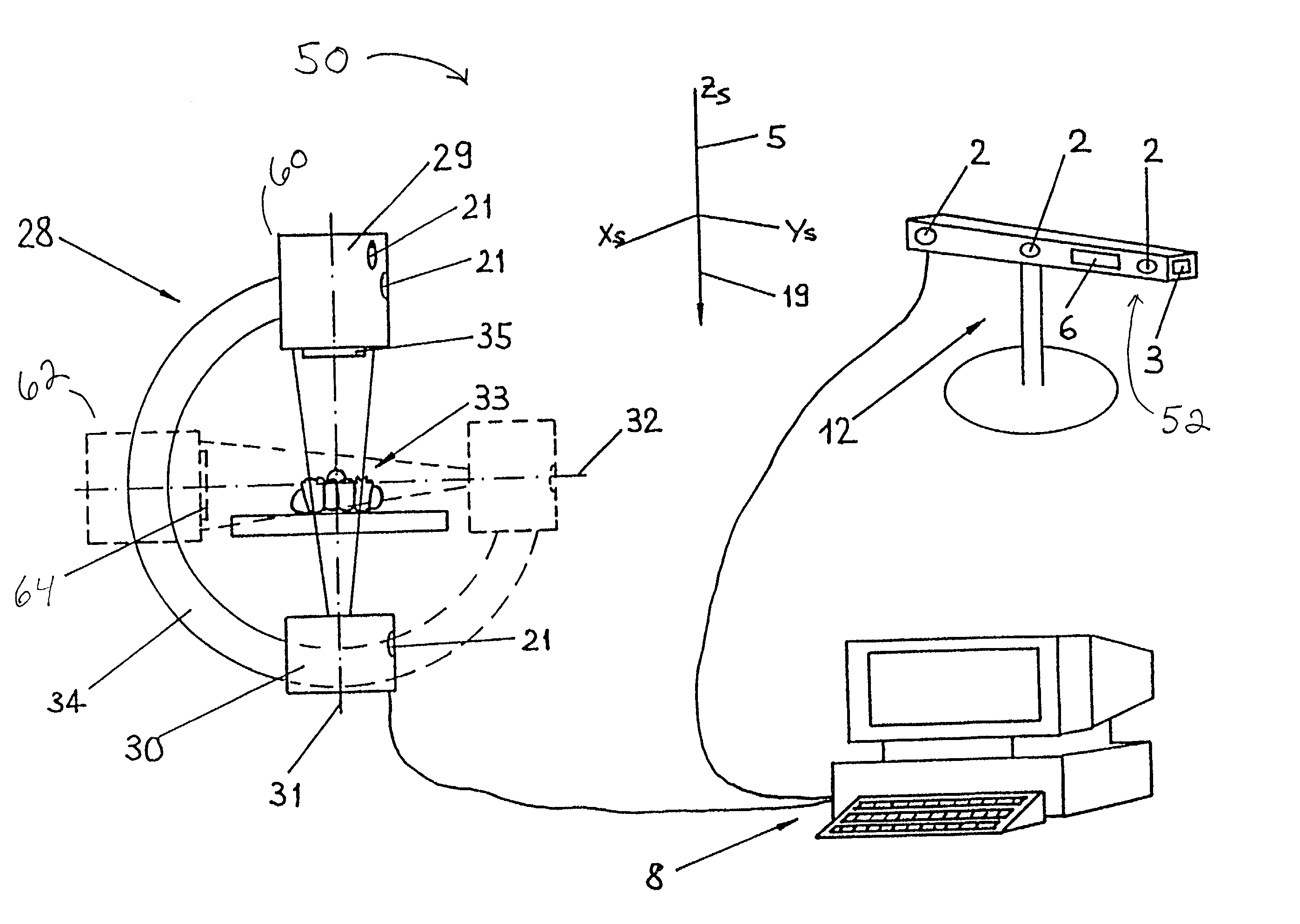
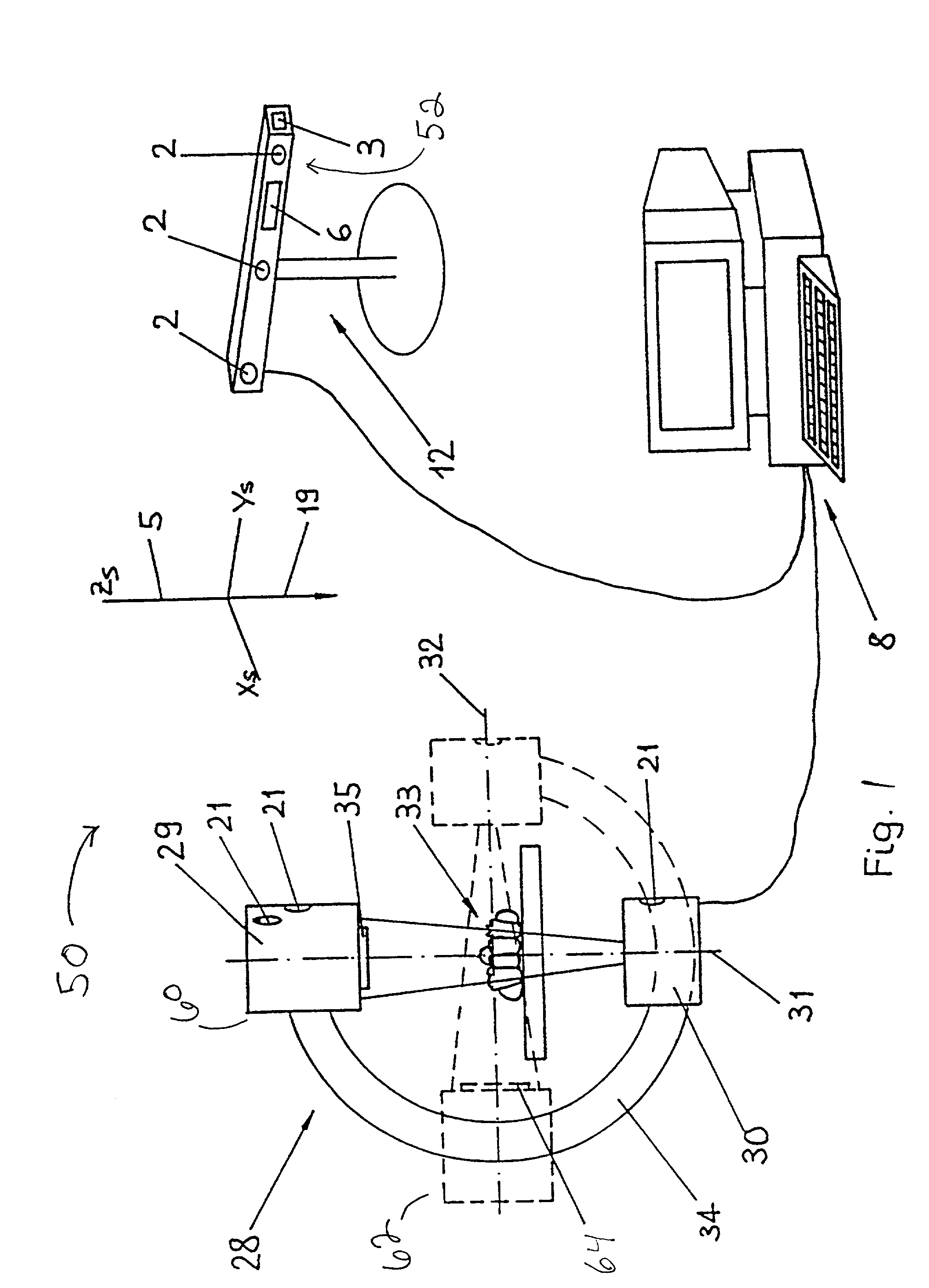
[0031]Referring to FIG. 1, an imaging system 50 includes an imager 28, which is configured to obtain one or more images of an object, such as a human 33 or other animal.

[0032]The images may include gravity induced errors, such as image distortions caused by gravity induced deformations of the imager, including mechanical deformations in the shape or position of the imager. According to the present invention, the gravity induced errors are correctable upon obtaining position data indicative of the position and orientation of the imager with respect to a gravity vector 19 local to the imager. The position data may include imager position data indicative of the position and orientation of imager 28 and gravity vector data indicative of the direction of gravity vector 19. A position measurement device 12 provides the imager position data and a gravity vector determination device 52, which may be integral with position measurement device 12, provides the in-situ gravity vector data. A co...


PUM


Abstract

The present invention relates to an imaging system for obtaining an image correctable for the presence of a gravity induced image error. The imaging system includes an imager to obtain an image of an object and a position measurement device to obtain position data indicative of a gravity-induced deformation of the imager. The position data may include gravity vector data indicative of an orientation of a gravity vector.

Description

RELATED APPLICATIONS[0001]This application is a continuation of National stage of application no. PCT / CH99 / 00183, May 3, 1999, which application is incorporated herein in its entirety.FIELD OF THE INVENTION[0002]The invention relates to a system and method for obtaining an image of an object. In particular, the invention relates to a system and method for obtaining an image corrected for the presence of a distortion caused by a gravity induced deformation of an imager used to obtain the image.BACKGROUND OF THE INVENTION[0003]The use of measuring instruments and imaging appliances often necessitates changes in the position or orientation of the measuring instrument depending on the type of measurement to be taken. For example, imagers or for obtaining x-ray images, such as the mobile or swivel-mounted x-ray imagers commonly used in surgery may be used to obtain images with the apparatus at different positions. Image intensifiers and c-arm appliances are examples of such imagers.[0004...

Claims


Application Information

Patent Timeline
IPC IPC(8): G06K9/40G06K9/36G01C9/00A61B6/00A61B6/08G01B11/00G01B11/16G01B15/00G01B21/00G01C9/06G01C19/00
CPCA61B6/08G01B11/16A61B6/583A61B6/547A61B6/4441
Inventor HOFSTETTER, ROBERTGUGGENHEIM, NICOLASSCHERRER, JOSE L.
Owner AO TECH AG
Why Eureka
Try Eureka