Internal combustion engine with variable compression ratio and valve characteristics

a technology of compression ratio and internal combustion engine, which is applied in the direction of combustion engine, valve arrangement, machine/engine, etc., can solve the problems of reducing engine efficiency, reducing fuel economy, and reducing fuel economy, so as to improve engine efficiency and fuel economy.

Active Publication Date: 2007-10-09
TOYOTA JIDOSHA KK
View PDF10 Cites 31 Cited by
  • Summary
  • Abstract
  • Description
  • Claims
  • Application Information

AI Technical Summary

Benefits of technology

[0009]It is an object of the invention to prevent collision between a piston and a valve (intake or exhaust valve) when valve characteristics control of the valve and compression ratio control are performed, and thereby improve the engine efficiency and the fuel economy when collision between the valve and the piston is being avoided.
[0013]When the compression ratio is set to the upper variation limit compression ratio, the controlled valve may collide with the piston. Therefore, if the realized compression ratio is larger than the upper variation limit compression ratio, the controlled valve collides with the piston. If the realized compression ratio is equal to or smaller than the upper variation limit compression ratio, the controlled valve does not collide with the piston. Therefore, according to the invention having the aforementioned structure, when the target compression ratio exceeds the upper variation limit compression ratio, the target compression ratio is limited to or below the upper variation limit compression ratio, and the compression ratio control mechanism is controlled to achieve the upper variation limit compression ratio that is smaller than the target compression ratio, rather than the target compression ratio. This makes it possible to prevent the controlled valve operating with the realized valve characteristics from colliding with the piston. Furthermore, when the compression ratio is controlled in the above manner, the compression ratio can be increased up to the upper variation limit compression ratio at which the collision is avoided, even though the upper variation limit compression ratio is smaller than the target compression ratio. As a result, the fuel economy improves as well as the engine efficiency. In addition, when the target compression ratio is equal to or smaller than the upper variation limit compression ratio, the compression ratio control mechanism is controlled so as to achieve the target compression ratio. Therefore, even in this case, the controlled valve operating with the realized valve characteristics can be prevented from colliding with the piston, and the internal combustion engine can be operated at the target compression ratio. As a result, both of the engine efficiency and fuel economy improve.

Problems solved by technology

However, as the compression ratio increases as a result of such compression ratio control, the top dead center of the piston approaches the valves.
According to theses methods, however, it is considered that the following problems may occur when the above-stated controls are being implemented to prevent collision between the piston and the valve.
Specifically, regarding the former method, when the valve lift of the intake valve is reduced and / or the valve timing of the intake valve is retarded to prevent collision with the piston, the charge efficiency of air-fuel mixture may decrease and thus the engine efficiency.
Regarding the latter method, when the compression ratio is reduced towards the minimum compression ratio to prevent collision between the piston and the valve, the temperature of air-fuel mixture may not sufficiently increase, which reduces the fuel economy.

Method used


Image

  • Internal combustion engine with variable compression ratio and valve characteristics
  • Internal combustion engine with variable compression ratio and valve characteristics
  • Internal combustion engine with variable compression ratio and valve characteristics

Examples


Embodiment Construction

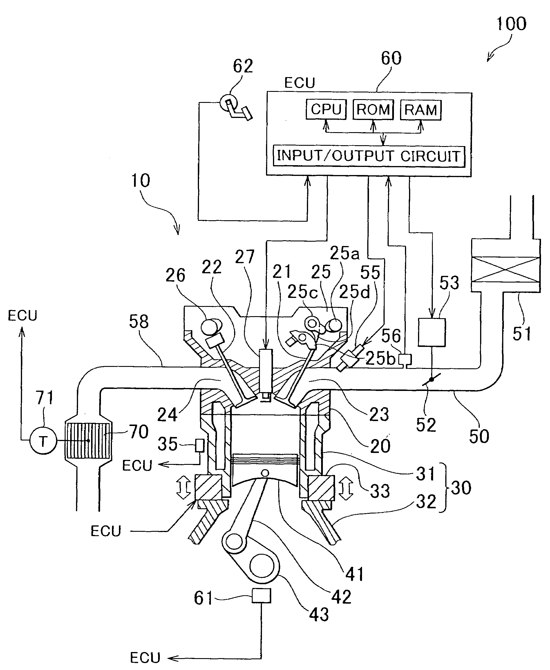
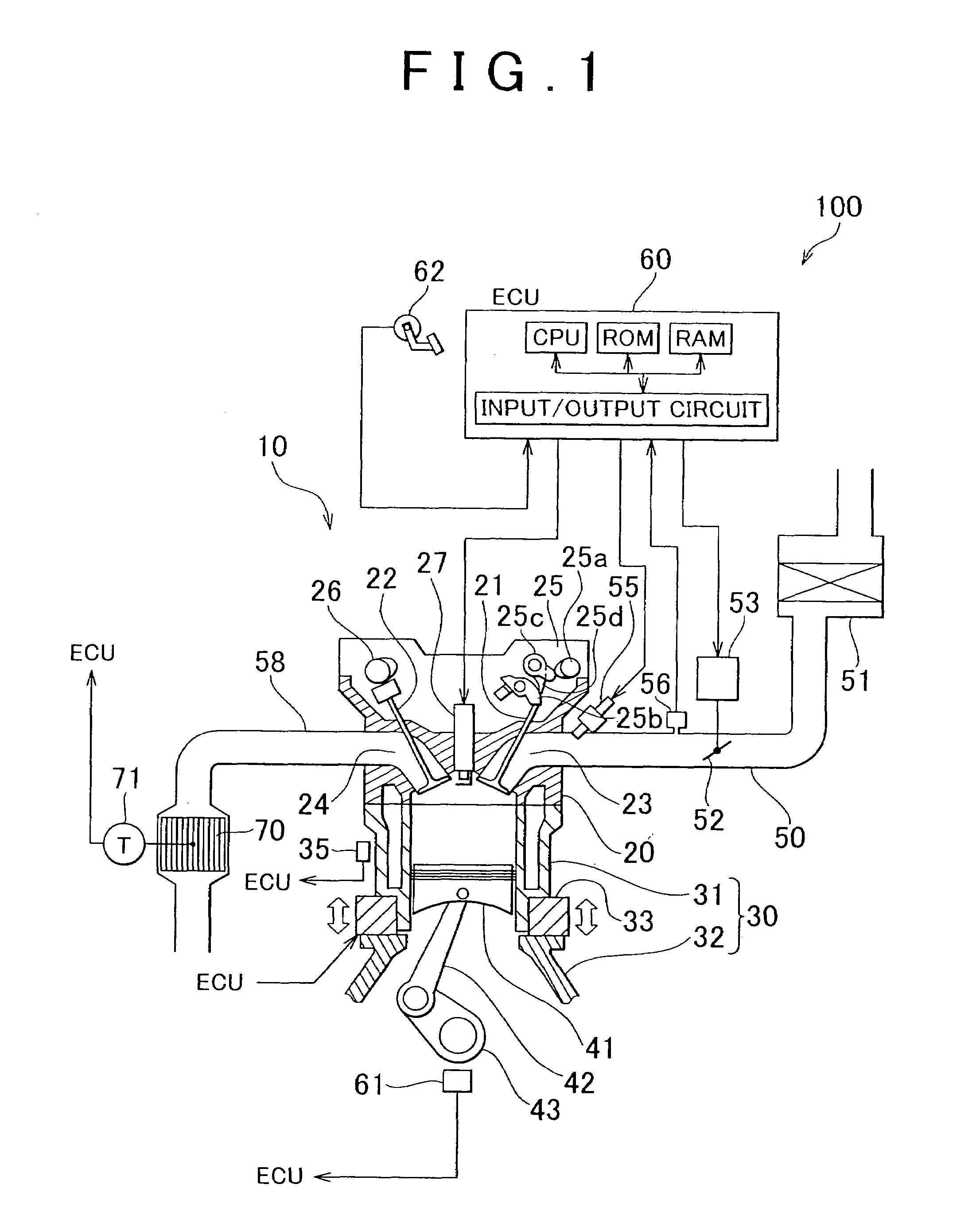
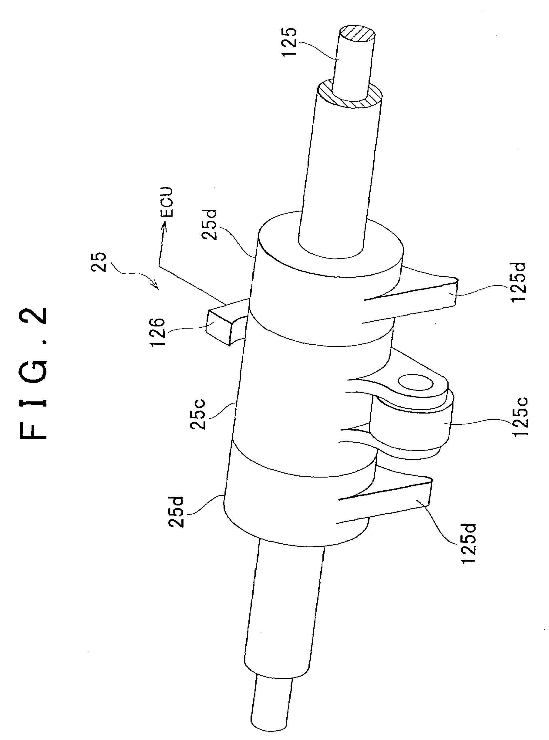
[0025]Exemplary embodiments of the invention will be described with reference to the drawings. FIG. 1 is a view schematically showing the construction of a gasoline engine 100 of the embodiment, and FIG. 2 is a view schematically showing the main portion of a cam mechanism that variably controls the valve characteristics. The engine in the embodiment is mounted on a vehicle.

[0026]A-1. Engine Structure:

[0027]The engine 100 includes an engine main unit 10, and the engine main unit 10 includes a cylinder head 20 and a cylinder block 30.

[0028]The cylinder block 30 includes an upper block 31 and a lower block 32. The upper block 31 serves as cylinders, and the lower block 32 serves as a crankcase. A piston 41 is provided in each of the cylinders, and a crankshaft 43 is provided in the crankcase. The piston 41 and the crankshaft 43 are connected to each other through a connecting rod 42 that converts the reciprocating motion of the piston 41 into the rotary motion of the crankshaft 43. Th...


PUM


Abstract

When controlling the valve characteristics of an intake valve and changing the compression ratio, an upper variation limit compression ratio, which is the upper limit of the variation of compression ratio, is determined according to the actual valve characteristics of the intake valve characteristics control. The upper variation limit compression ratio is set to a valve at which the intake valve does not collide with the piston. When a target compression ratio corresponding to the operation state of the engine is larger than the upper variation limit compression ratio, the compression ratio is set to the upper variation limit compression ratio that is smaller than the target compression ratio. Thus, collision between the intake valve and the piston can be prevented while allowing the compression ratio to be increased up to the maximum compression ratio of the range where the collision does not occur.

Description

INCORPORATION BY REFERENCE[0001]The disclosure of Japanese Patent Application No. 2005-316674 filed on Oct. 31, 2005, including the specification, drawings and abstract is incorporated herein by reference in its entirety.BACKGROUND OF THE INVENTION[0002]1. Field of the Invention[0003]The invention relates to an internal combustion engine in which the compression ratio and valve characteristics are variable.[0004]2. Description of the Related Art[0005]In recent years, various controls for controlling internal combustion engines have been proposed and employed to further improve the engine efficiency. The engine efficiency improves, for example, when the charging efficiency of air-fuel mixtures improves and when the compression ratio at which fuel is burned increases. Thus, it has been proposed to variably control the compression ratio in a combustion chamber, as well as the valve characteristics of the intake and exhaust valves, on the basis of the operation state of the internal com...

Claims


Application Information

Patent Timeline
Patent Type & Authority Patents(United States)
IPC IPC(8): F02B75/04F02D13/00F01L1/34
CPCF01L1/053F01L1/185F01L13/0021F02D15/04F02D13/0203Y02T10/18Y02T10/12
Inventor KAMIYAMA, EIICHIAKIHISA, DAISUKE
Owner TOYOTA JIDOSHA KK
Why Eureka
Try Eureka