Supercharge Your Innovation With Domain-Expert AI Agents!

Combustion-gas recirculation system

a recirculation system and combustion gas technology, applied in the field of recirculation systems, can solve the problems of increasing the cost and maintenance requirements of the engine, compromising the performance of the engine, and noxious combustion gases produced by the engin

Active Publication Date: 2007-10-09
CATERPILLAR INC
View PDF15 Cites 8 Cited by
  • Summary
  • Abstract
  • Description
  • Claims
  • Application Information

AI Technical Summary

Benefits of technology

The patent describes a system for recircling combustion gas in an engine. The system includes a mixing chamber with an open inlet channel that extends into the chamber. The open inlet channel is connected to the engine's air-intake system and allows air to enter the chamber at near-atmospheric pressure. The system also includes a duct for directing air and a second gas to the combustion chamber. The technical effect of this system is to improve engine performance and efficiency by optimizing the air and gas mixing process in the combustion chamber.

Problems solved by technology

Some of the combustion gases produced by an engine may be noxious.
This restriction may compromise the performance of the engine by reducing the airflow to the combustion chambers of the engine.
The inclusion of the butterfly valve may also increase cost and maintenance requirements of the engine.

Method used


Image

  • Combustion-gas recirculation system
  • Combustion-gas recirculation system
  • Combustion-gas recirculation system

Examples


Embodiment Construction

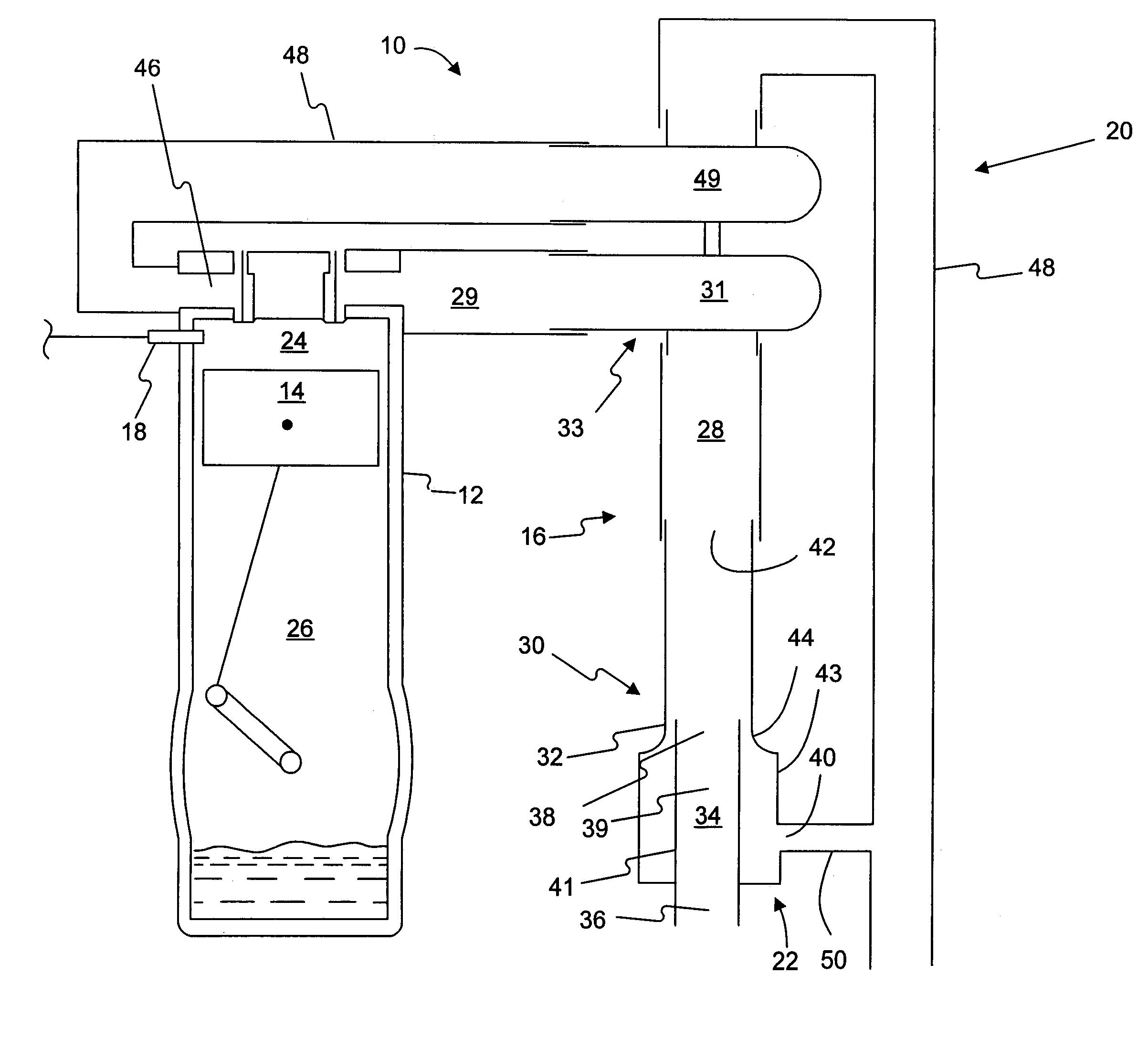
[0012]FIG. 1 provides a schematic illustration of an engine 10 according to an exemplary disclosed embodiment. Engine 10 may include a housing 12, a working member 14, an air-intake system 16, a fuel system 18, an exhaust system 20, and a combustion-gas recirculation system 22.

[0013]Working member 14 may be movably supported in an interior of housing 12 such that it separates a combustion chamber 24 from a non-combustion chamber 26. As shown in FIG. 1, working member 14 may be a piston supported in a cylindrical portion of housing 12. Housing 12, working member 14, combustion chamber 24, and non-combustion chamber 26 are not limited to the configuration shown in FIG. 1. Working member 14 may have any shape and may be movably supported within housing 12 in any manner such that it separates combustion chamber 24 from non-combustion chamber 26. For example, working member 14 may be a rotor that rotates within housing 12, as in a Wankel type internal combustion engine.

[0014]Air-intake s...


PUM


Abstract

A combustion-gas recirculation system has a mixing chamber with a mixing-chamber inlet and a mixing-chamber outlet. The combustion-gas recirculation system may further include a duct connected to the mixing-chamber inlet. Additionally, the combustion-gas recirculation system may include an open inlet channel with a solid outer wall. The open inlet channel may extend into the mixing chamber such that an end of the open inlet channel is disposed between the mixing-chamber inlet and the mixing-chamber outlet. Furthermore, air within the open inlet channel may be at a pressure near or below atmospheric pressure.

Description

GOVERNMENT RIGHTS[0001]This invention was made with Government support under the terms of Contract No. DE-FC26-01CH11079 awarded by the Department of Energy. The Government may have certain rights in this invention.TECHNICAL FIELD[0002]The present disclosure relates to a recirculation system and, more particularly, to a combustion-gas recirculation system for an engine.BACKGROUND[0003]Engines produce power by combusting fuel and air in a combustion chamber to produce high-pressure combustion gases that drive a working member of the engine, such as a piston. Some of the combustion gases produced by an engine may be noxious. The combustion gases produced during operation of an engine may travel from the combustion chamber to the atmosphere, either through an exhaust system or through other portions of the engine, such as a crankcase.[0004]At least one internal combustion engine has been conceived with provisions for recirculating at least a portion of the combustion gases produced by ...

Claims


Application Information

Patent Timeline
Patent Type & Authority Patents(United States)
IPC IPC(8): F02M25/07F02M25/00
CPCF02M25/06F02M25/0709F01M13/022F02M25/0722F01M2013/026Y02T10/121F02M26/06F02M26/19Y02T10/12
Inventor BALDWIN, DARRYL DEAN
Owner CATERPILLAR INC
Features
  • R&D
  • Intellectual Property
  • Life Sciences
  • Materials
  • Tech Scout
  • Unparalleled Data Quality
  • Higher Quality Content
  • 60% Fewer Hallucinations
Learn More