Contact protector for electrical connectors

a technology for protecting electrical connectors and connectors, applied in the direction of coupling device details, coupling device connections, coupling protective earth/shielding arrangements, etc., can solve the problems of destroying an entire motherboard or daughtercard, not all electrical contacts of the electrical connector will engage properly, and the electrical connector may not properly connect with the contacts of the receptacle connector

Active Publication Date: 2007-10-09
FCI AMERICAS TECH LLC
View PDF15 Cites 69 Cited by
  • Summary
  • Abstract
  • Description
  • Claims
  • Application Information

AI Technical Summary

Benefits of technology

[0004]A contact protector for an electrical header connector assembly is disclosed. The contact protector may include a mating side that mimics a mating side of a receptacle connector that is complementary to the header connector assembly. Such a housing may be inserted into the header connector assembly to protect the mating pins during shipment. The contact protector may include a pull portion, which may be, for example, a handle attached to the contact protector or a piece of tape taped to the contact protector, so that the user can remove the contact protector from the header connector assembly.

Problems solved by technology

The electrical connector, therefore, may not properly connect with receptacle connector contacts.
That is, not all electrical contacts of the electrical connector will engage properly into the complementary contacts of the receptacle connector.
Moreover, in many cases, a damaged electrical connector can ruin an entire motherboard or daughtercard.

Method used


Image

  • Contact protector for electrical connectors
  • Contact protector for electrical connectors
  • Contact protector for electrical connectors

Examples


Embodiment Construction

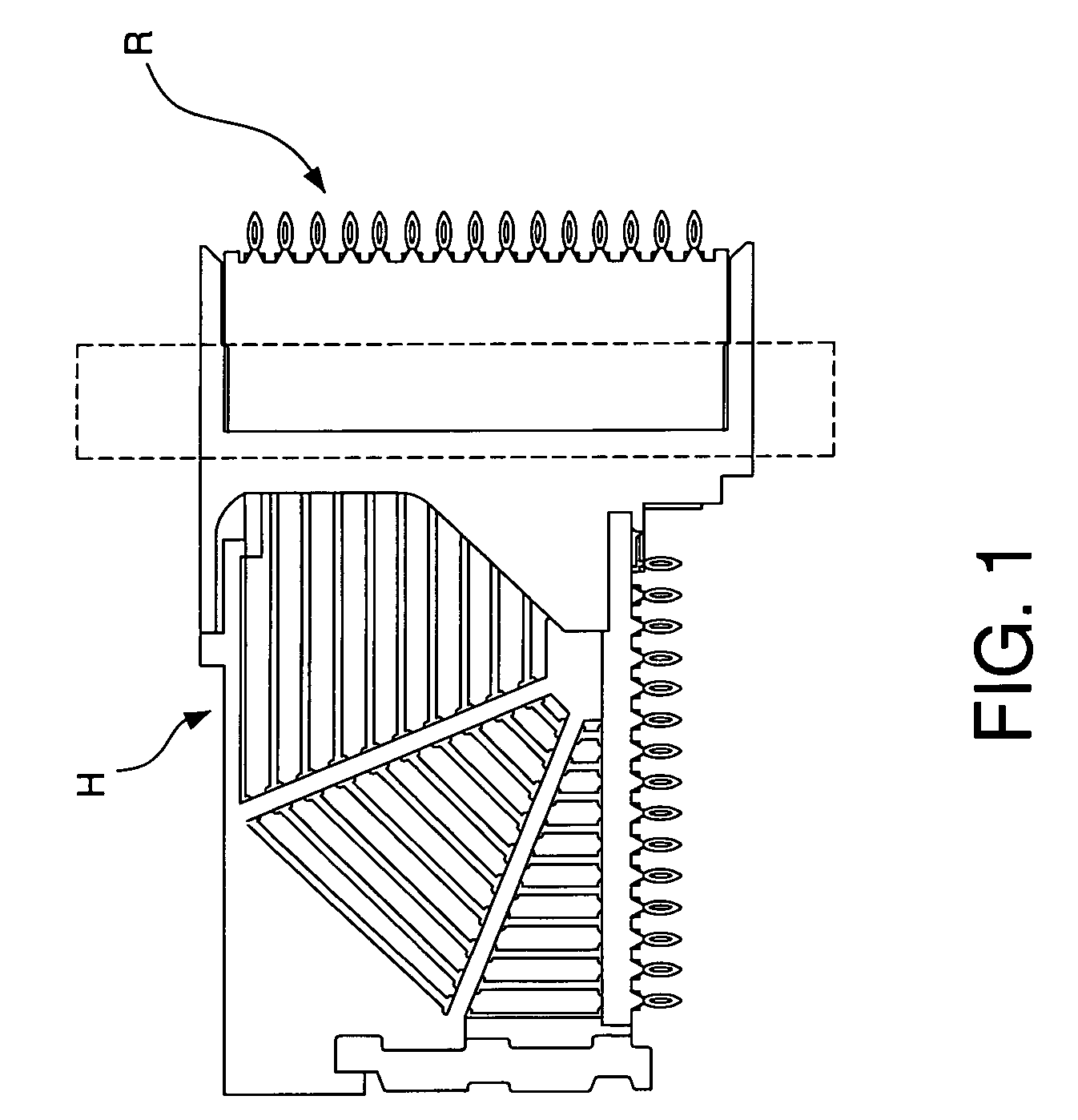
[0017]FIG. 1 generally depicts a header connector assembly H engaged with a receptacle connector R. A mating interface area is designated generally with the reference I and refers to the mating interface between the header connector assembly H and the receptacle connector R.

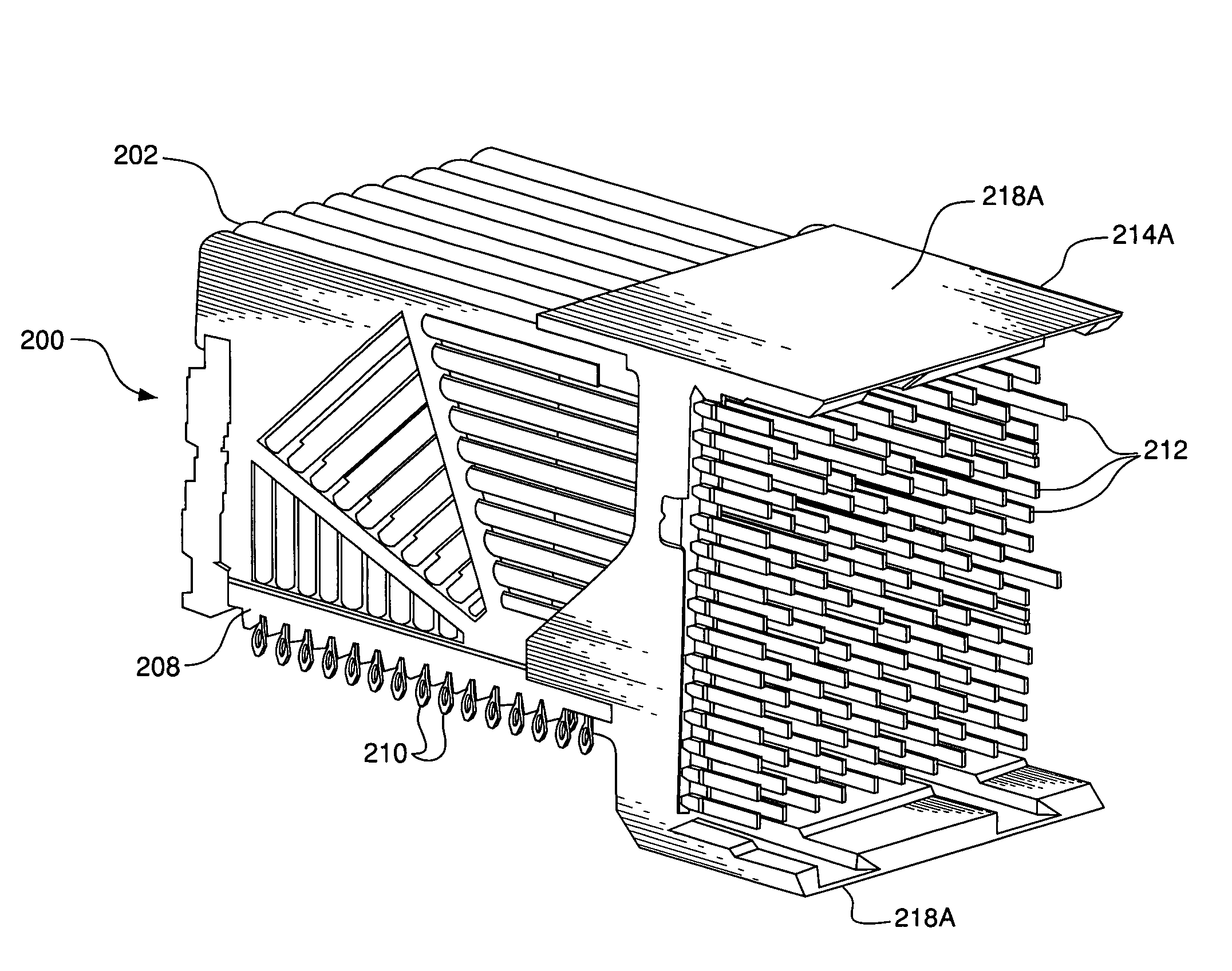
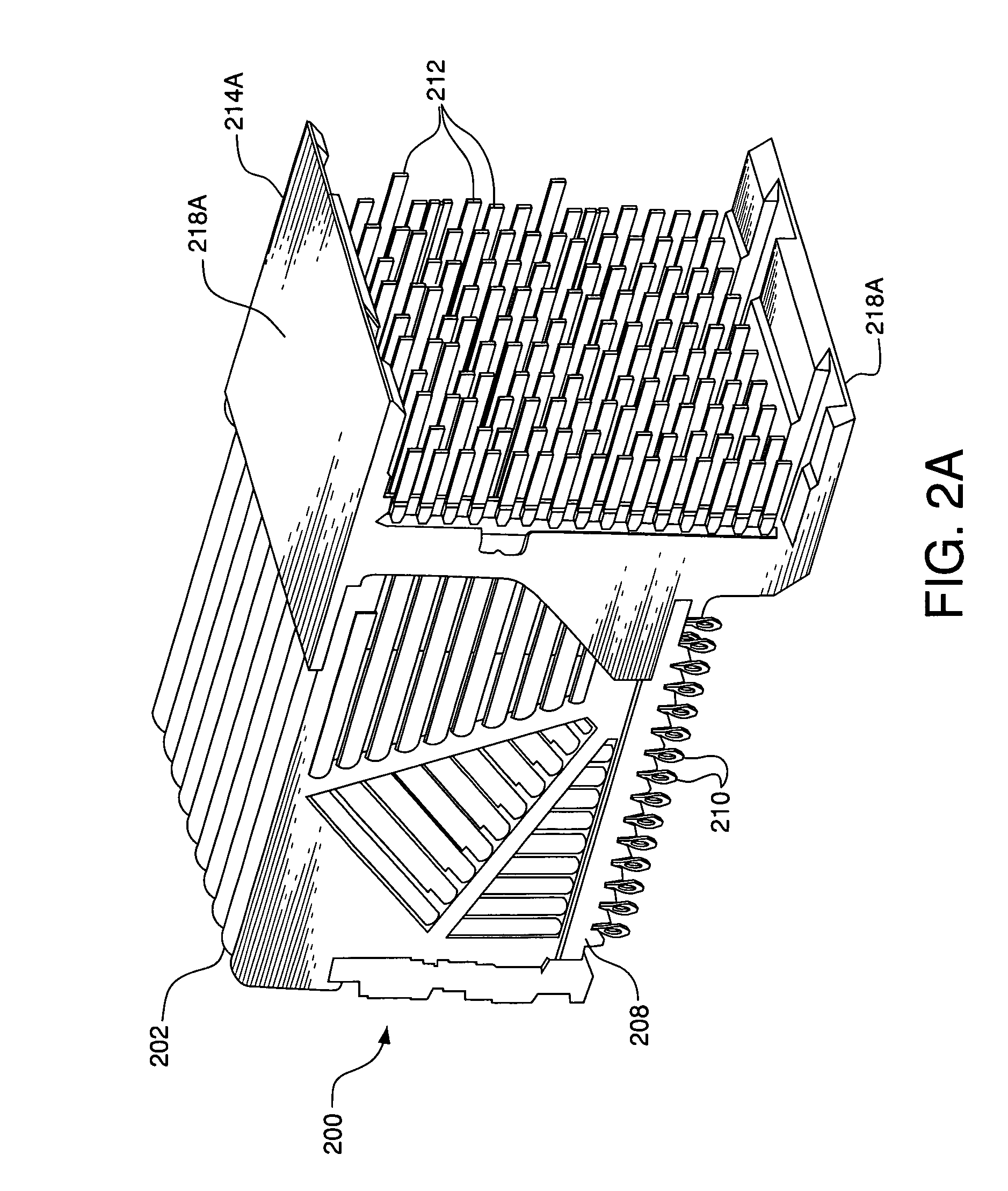
[0018]FIGS. 2A and 2B depict example embodiments of a header connector assembly. As shown, the header connector assembly 200 may include a plurality of insert molded leadframe assemblies (IMLAs) 202. FIGS. 3A and 3B are side views of example embodiments of an IMLA 202 according to the invention. An IMLA 202 includes a contact set 206 of electrically conductive contacts 204, and an IMLA frame 208 through which the contacts 204 at least partially extend. An IMLA 202 may be used, without modification, for single-ended signaling, differential signaling, or a combination of single-ended signaling and differential signaling. Each contact 204 may be selectively designated as a ground contact, a single-ended signal condu...


PUM


Abstract

A protective housing removably attached to an electrical connector to prevent damage to contacts of the connector during, for example, shipping or handling of the electrical connector before the connector is connected with an electrical device such as a second electrical connector. The contact protector may include a pull portion of adhesive tape that abuts a housing of the electrical connector, creating an interference fit. The contact protector may include a handle integrated with the contact protector to facilitate removal of the contact protector from the electrical connector.

Description

CROSS-REFERENCE TO RELATED APPLICATIONS[0001]This application claims benefit under 35 U.S.C. § 119(e) of provisional U.S. patent application No. 60 / 605,942, filed Aug. 31, 2004, entitled “Mating Pin Protection Methods,” the disclosure of which is incorporated herein by reference in its entirety.FIELD OF THE INVENTION[0002]Generally, the invention relates to electrical connectors. More particularly, the invention relates to methods for protecting electrical connector electrical contacts during shipment, handling, processing, and pre-mating of the electrical contacts.BACKGROUND OF THE INVENTION[0003]A male, plug, or header electrical connector typically includes an arrangement of electrical contacts or mating pins. The electrical contacts may extend beyond a housing of the connector or a frame of a lead frame assembly and thus are partially exposed. Sometimes, during handling or shipment of the electrical connector, exposed end portions of the electrical contacts bend. Consequently, d...

Claims


Application Information

Patent Timeline
Patent Type & Authority Patents(United States)
IPC IPC(8): H01R12/00
CPCH01R13/443H01R23/7073H01R23/688H01R13/514H01R12/724H01R13/6586
Inventor MINICH, STEVEN E.
Owner FCI AMERICAS TECH LLC
Why Eureka
Try Eureka