
Thermal spraying powder

a technology of thermal spraying powder and thermal spray coating, which is applied in the direction of cellulosic plastic layered products, natural mineral layered products, transportation and packaging, etc., can solve the problems of insufficient consideration of the porosity of thermal spray coating, the near-by boundary surface between the base material and the thermal spray coating is likely to delaminate or detach from the base material

Inactive Publication Date: 2007-10-09
FUJIMI INCORPORATED
View PDF5 Cites 8 Cited by
  • Summary
  • Abstract
  • Description
  • Claims
  • Application Information

AI Technical Summary

Benefits of technology

[0005]Accordingly, it is an objective of the present invention to provide a thermal spraying powder that reliably forms a thermal spray coating that is suitable for use where the thermal spray coating is subjected to a thermal shock in a corrosive atmosphere or an oxidative atmosphere and for use where the thermal spray coating is subjected to a thermal shock in a state where the thermal spray coating contacts a member that has reactivity to a base material.

Problems solved by technology

However, if the density is too high, when the thermal spray coating is subjected to a thermal shock, for example, when a heating process with plasma or a heater and subsequent cooling process are repeated, the thermal spray coating is likely to delaminate or detach from the base material.
Meanwhile, if the density of the thermal spray coating is too low, the base material in the vicinity of the boundary surface between the base material and the thermal spray coating is corroded or oxidized, because the ambient gas reaches the base material through pores in the thermal spray coating.
In this respect, in the technique disclosed in the above publication No. 2002-80954, consideration for the porosity of the thermal spray coating is inadequate.
Therefore, it is difficult to obtain a thermal spray coating that is suitable for use where the thermal spray coating is subjected to a thermal shock in a corrosive atmosphere or an oxidative atmosphere and for use where the thermal spray coating is subjected to a thermal shock in a state where the thermal spray coating contacts a member that has reactivity to the base material.

Method used


Image

  • Thermal spraying powder

Examples


Embodiment Construction

[0010]One embodiment of the present invention will now be described.

[0011]A thermal spraying powder of the preferred embodiment is substantially formed of granulated and sintered particles of an yttrium-aluminum double oxide that is obtained by granulating and sintering a raw powder containing yttrium and aluminum, and is used for, for example, forming a thermal spray coating through plasma spraying.

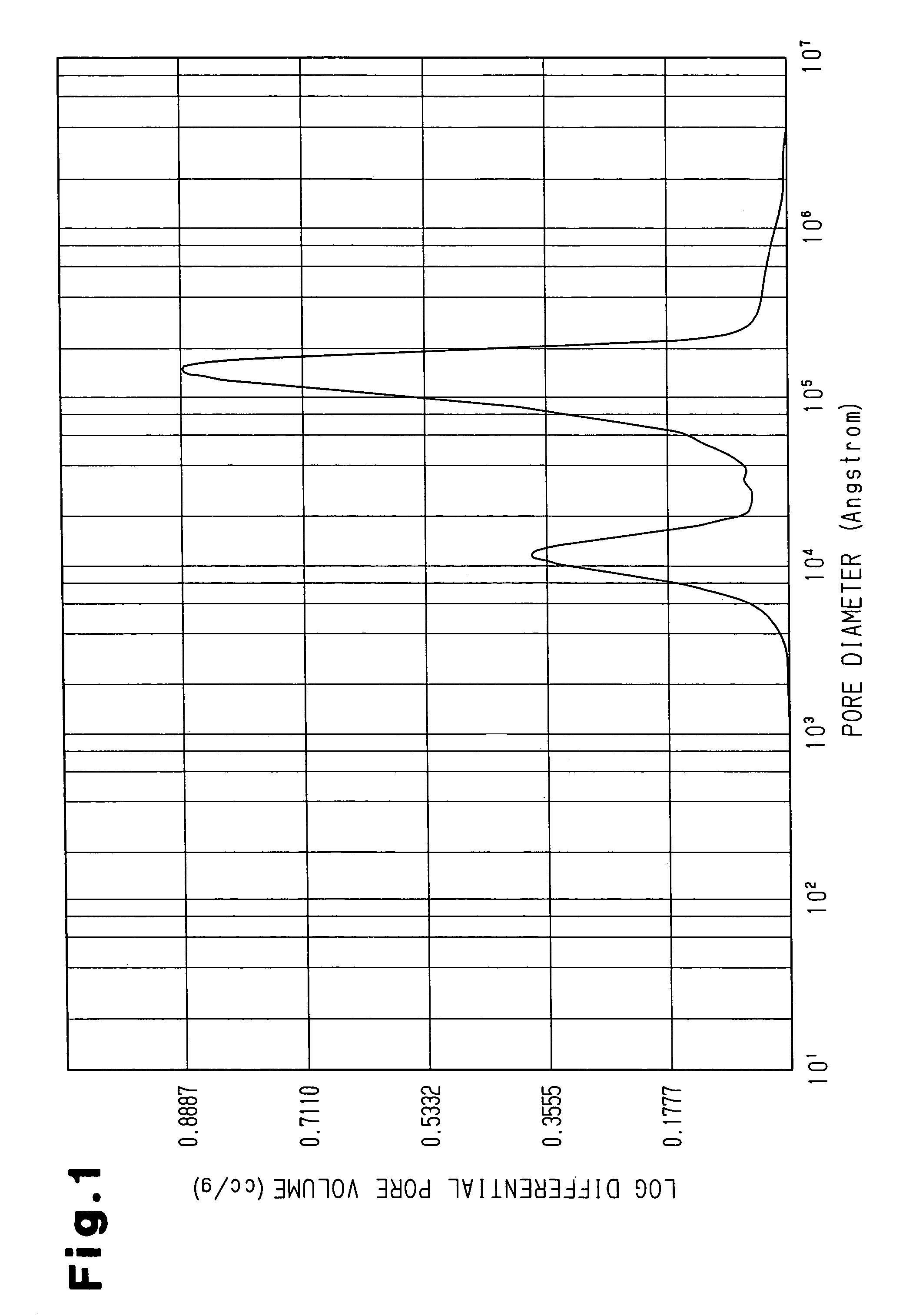
[0012]When the total volume of fine pores having a diameter of 6 μm or less in one gram of the granulated and sintered particles is less than 0.06 cm3, the thermal spray coating formed of the thermal spraying powder is likely to delaminate or detach from the base material when subjected to a thermal shock. This is because the density of the thermal spray coating formed of the thermal spraying powder becomes too high, and cracks are easily formed in the thermal spray coating by thermal expansion and thermal shrinkage. Furthermore, since the granulated and sintered particles with the total...


PUM

PropertyMeasurementUnit
diameteraaaaaaaaaa
pore size distributionaaaaaaaaaa
particle sizeaaaaaaaaaa

Abstract

A thermal spraying powder includes granulated and sintered particles of an yttrium-aluminum double oxide obtained by granulating and sintering a raw powder containing yttrium and aluminum. The total volume of fine pores having a diameter of 6 μm or less in one gram of the granulated and sintered particles is 0.06 to 0.25 cm3. The thermal spraying powder reliably forms a thermal spray coating that is suitable for use where the thermal spray coating is subjected to a thermal shock in a corrosive atmosphere or an oxidative atmosphere and for use where the thermal spray coating is subjected to a thermal shock in a state where the thermal spray coating contacts a member that has reactivity to a base material.

Description

BACKGROUND OF THE INVENTION[0001]The present invention relates to a thermal spraying powder containing granulated and sintered particles of an yttrium-aluminum double oxide.[0002]When using a member formed of a material that has low corrosion resistance and oxidation resistance in a corrosive atmosphere or an oxidative atmosphere, a coating formed of a material that has a superior corrosion resistance and oxidation resistance such as an yttrium-aluminum double oxide is generally provided on the surface of the member. For example, Japanese Laid-Open Patent Publication No. 2002-80954 discloses a technique for forming a thermal spray coating of an yttrium-aluminum double oxide on the surface of a base material by plasma spraying granulated and sintered particles of an yttrium-aluminum double oxide.[0003]To suppress corrosion and oxidation of the base material by ambient gas, the thermal spray coating desirably has a high density, or a low porosity. However, if the density is too high, ...

Claims


Application Information

Patent Timeline
Patent Type & Authority Patents(United States)
IPC IPC(8): B32B5/16
CPCC23C4/105Y10T428/2982Y10T428/2995Y10T428/2991Y10T428/2993C23C4/11B22F1/00
Inventor KITAMURA, JUNYAMIZUNO, HIROAKIITSUKAICHI, TSUYOSHI
Owner FUJIMI INCORPORATED
Learn More