Magnetic element

a technology of magnetic elements and conductors, applied in the field of magnetic elements, can solve the problems of affecting the characteristics of magnetic elements, short or so forth, slight vibration, etc., and achieve the effect of reducing the outside dimension and facilitating the position of conductors

Active Publication Date: 2007-10-09
SUMIDA CORP
View PDF11 Cites 87 Cited by
  • Summary
  • Abstract
  • Description
  • Claims
  • Application Information

AI Technical Summary

Benefits of technology

[0010]When it is thus configured, the conductor and the mounting terminal are formed integrally, so that the downward extension and mounting portion of the mounting terminal can be formed by bending the conductor. Further, the mounting portion is fitted into the bottom surface recessed portion provided on the bottom surface of the core. Therefore, the positioning of the conductor can be performed easily and surely by simply fitting the mounting portion in the bottom surface recessed portion. Furthermore, the mounting portion is fitted into the bottom surface recessed portion, so that the conductor can reduce its shake. Moreover, the positioning of the conductor is performed by fitting the mounting portion in the bottom surface recessed portion, so that the fluctuation in the characteristics of the magnetic elements can be reduced, facilitating the property designing. In addition, the thickness of the magnetic element can be reduced to the extent that the mounting portion is fitted in the bottom surface recessed portion, so that the height reduction and downsizing of the magnetic element are enabled.
[0012]When it is thus configured, the downward extension is fitted in the end surface recessed portion provided on the end surface of the core in addition to the bottom surface recessed portion. Therefore, the positioning of the conductor can be performed more easily and surely. Further, by fitting the downward extension to the end surface recessed portion, the shaking of the conductor can be reduced. Furthermore, the positioning of the conductor is performed by fitting the downward extension in the end surface recessed portion, so that the fluctuation in the characteristics of the magnetic elements can be reduced, facilitating the property designing. In addition, the size in the longitudinal direction of the through hole of the magnetic element can be reduced to the extent that the downward extension is fitted in the end surface recessed portion, so that the downsizing of the magnetic element is enabled.
[0014]According to the present invention, it is possible to position a conductor easily in a magnetic element. Further, the magnetic element can reduce its outside dimension.

Problems solved by technology

However, for example, when two conductors are inserted through the hollow portion, a positional displacement between these two terminals causes a short or so forth, being undesirable.
Further, even if it is a single conductor, when the conductor has a space between an internal wall surface of the hollow portion and itself, a positional displacement of the terminal may lead to a slight vibration, being a problem.
Further, the positional displacement caused in the hollow portion of the conductor frequently affects the characteristics of the magnetic element.
Consequently, another problem with the respectively produced magnetic elements have different properties will arise as well.

Method used


Image

  • Magnetic element
  • Magnetic element
  • Magnetic element

Examples


Embodiment Construction

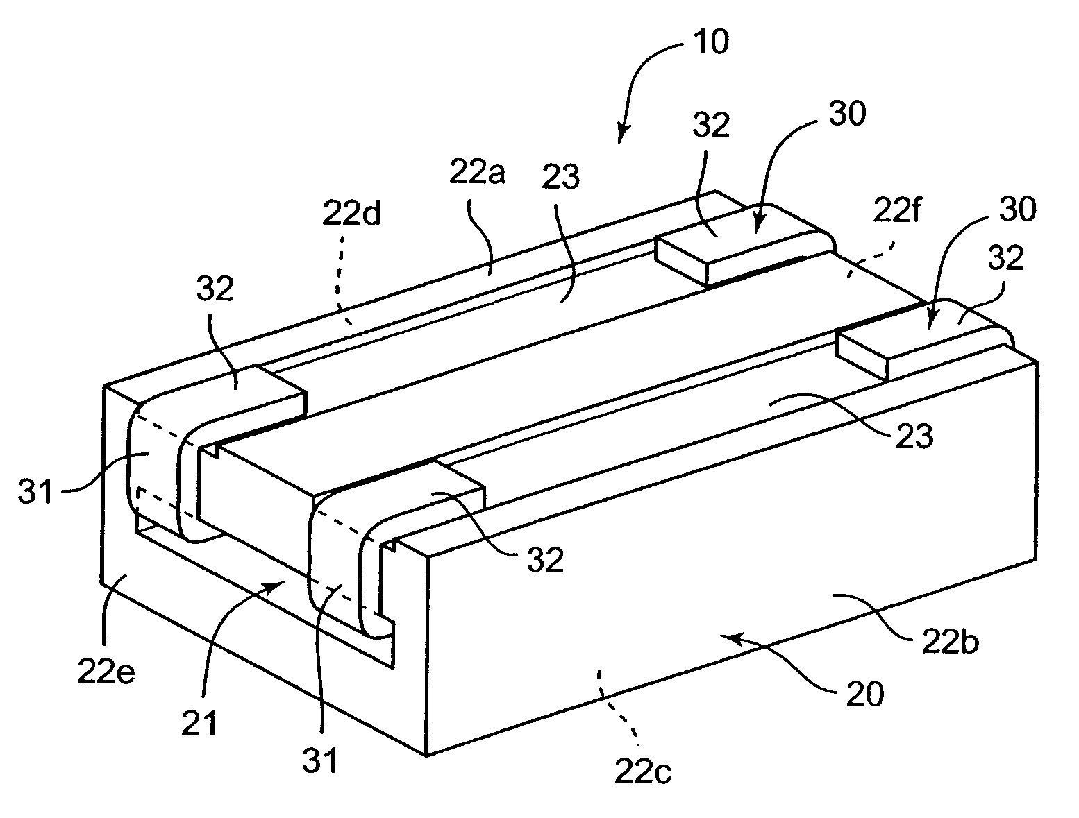
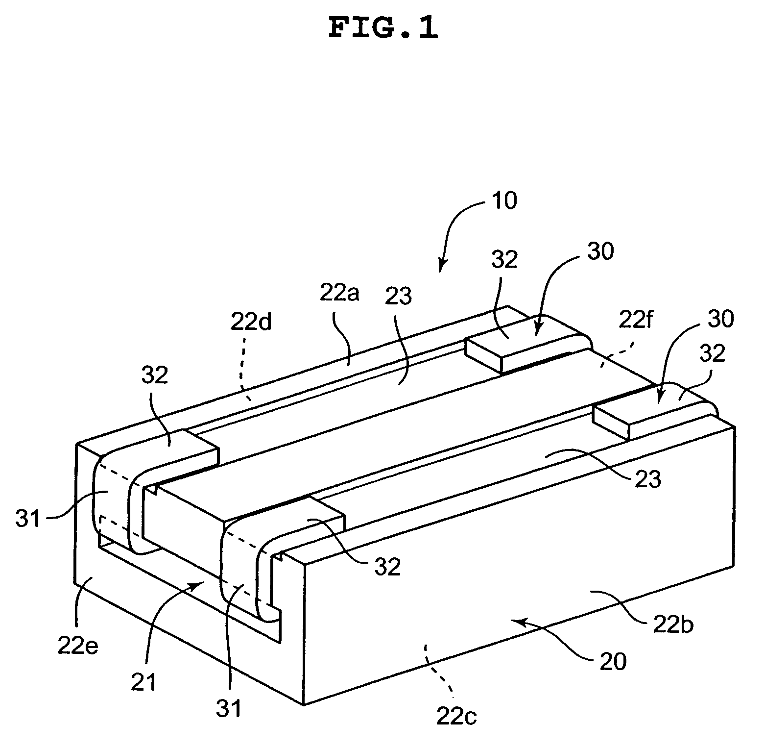
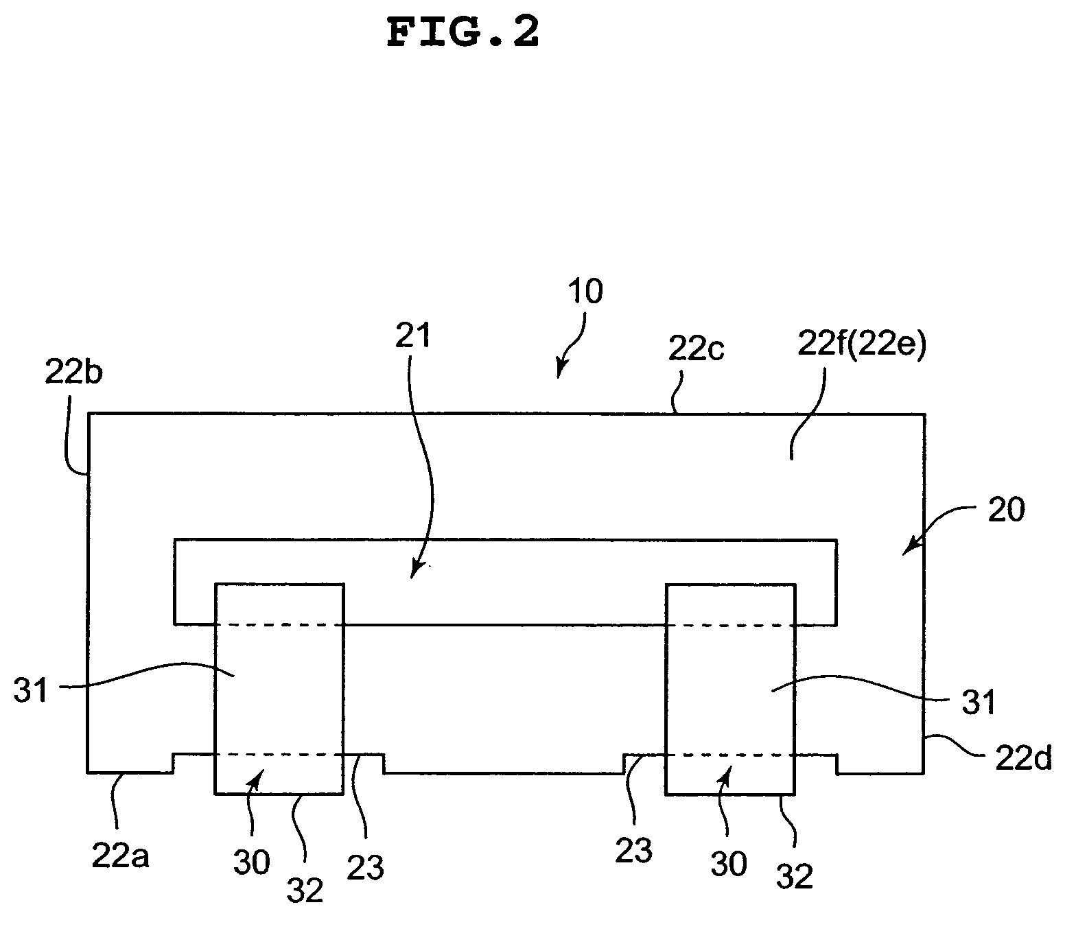
[0026]Hereinafter, a magnetic element 10 according to an embodiment of the present invention will be described based on FIGS. 1 to 3. FIG. 1 is a perspective view showing an entire configuration of the magnetic element 10 in which a bottom surface 22a is arranged to position upward. FIG. 2 is a front view showing the configuration of the magnetic element 10. Further, FIG. 3 is a sectional side view showing the configuration of the magnetic element 10.

[0027]Note that, in the description below, topside indicates an upper surface 22c side being distant from the later-described bottom surface 22a, and a bottom side indicates a side at which later-described bottom surface recessed portion 23 is provided. Further, a height direction indicates a vertical direction between the upper surface 22c and the bottom surface 22a in the magnetic element 10.

[0028]The magnetic element 10 according to the embodiment of the present invention includes a core 20 and conductors 30, as shown in FIG. 1 and s...


PUM

PropertyMeasurementUnit
heightaaaaaaaaaa
magneticaaaaaaaaaa
shapeaaaaaaaaaa

Abstract

The magnetic element includes a core (20) provided with a through hole (21) passing through a tubular portion, a linear conductor (30) having a plated surface, which is to be inserted through the through hole (21), and a mounting terminal with its one end side is electrically connected to the conductor and another end side positioning on a bottom surface (22a) of the core (20), the mounting terminal being mounted to an external mounting substrate facing the bottom surface (22a). Further, the conductor (30) is provided integrally with the mounting terminal composed of a downward extension (31) extending from the one end side of the conductor (30) to the bottom surface (22a) side and formed by bending itself and a mounting portion (32) positioning on the bottom surface (22a) and formed by bending itself. Furthermore, a certain number of bottom surface recessed portion(s) (23) is / are provided in the bottom surface (22a) to fit the mounting portion(s) (32) of the mounting terminal(s) therein corresponding to the number of the mounting terminal(s), in which the depth of the bottom surface recessed portion (23) is designed to be smaller than the thickness of the mounting portion (32).

Description

CROSS REFERENCE TO RELATED APPLICATIONS[0001]This application claims priority of Japanese Patent Application Number JP2004-307693, filed on Oct. 22, 2004, the complete disclosure of which is hereby incorporated by reference.FIELD OF THE INVENTION[0002]The present invention relates to a magnetic element used for various electric products such as a power supply section of a computer.DESCRIPTION OF THE RELATED ART[0003]For instance, in a power supply section or the like of a computer, a switching element that operates at a high frequency (driven at a high frequency) is used in a switching circuit. When the operating frequency is high in the switching circuit as described above, a magnetic element used in the circuit is required to have a slight inductance value. As one kind of the magnetic element having such a slight inductance value, there is one disclosed in Japanese Patent Number 3366916 (refer to FIG. 2, paragraph No. 0011 and so on) (Patent document 1).[0004]In the magnetic eleme...

Claims


Application Information

Patent Timeline
Patent Type & Authority Patents(United States)
IPC IPC(8): H01F5/00
CPCH01F17/06H05K3/3426H01F27/292H05K2201/09036Y02P70/50
Inventor SANO, KAN
Owner SUMIDA CORP
Why Eureka
Try Eureka