Power supply circuit, back-pack power supply module and circuit interrupter including the same

a power supply circuit and circuit technology, applied in emergency protective arrangements for limiting excess voltage/current, relays, instruments, etc., can solve problems such as large and heavy, conductors and various other parts, and large damage to circuit components and devices connected to the circui

Inactive Publication Date: 2007-10-09
EATON CORP
View PDF9 Cites 13 Cited by
  • Summary
  • Abstract
  • Description
  • Claims
  • Application Information

AI Technical Summary

Problems solved by technology

When an abnormal condition is reached, the latchable operating mechanism becomes unlatched, which causes the push rod to move to the open position.
Such circuit interrupters, being relatively large and heavy, are mounted on trucks for insertion into and removal from metal enclosures or cabinets in which they are housed.
Line faults at these high energy levels can cause extensive damage to circuit components and devices connected to the circuit, or to conductors and various other portions of the electrical energy distribution system.

Method used


Image

  • Power supply circuit, back-pack power supply module and circuit interrupter including the same
  • Power supply circuit, back-pack power supply module and circuit interrupter including the same
  • Power supply circuit, back-pack power supply module and circuit interrupter including the same

Examples


example 1

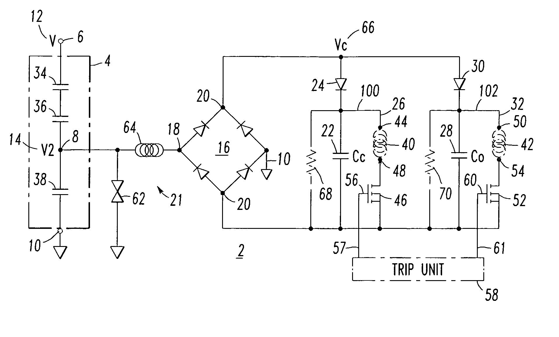
[0035]In this particular non-limiting example, the medium voltage (V) 12 is about 17.5 kVRMS at a suitable power line frequency (e.g., without limitation, 50 Hz; 60 Hz). The capacitors 34,36 are 0.01 μF, and the capacitor 38 is 0.33 μF. The resulting voltage (V2) 14 is about 261 volts RMS. The power supply circuit 2 functions under a wide range of operating conditions (e.g., without limitation, no charge on capacitors 22,28; charging; full charge; 17.5 kVRMS steady state; a 95 kV 1.2 μs pulse test condition).

example 2

[0036]As an alternative to Example 1, in which the two capacitors 34,36 are electrically connected in series, a single capacitor (not shown) having a suitable capacitance and voltage rating may be employed. Alternatively, other suitable parallel and / or series combinations of capacitors may be employed.

example 3

[0037]The MOV 62 prevents relatively high transient (e.g., momentary) values of voltage from reaching the circuit at, or downstream of, rectifier output 20. In this particular non-limiting example, the MOV 62 is rated at 275 VRMS.


PUM


Abstract

A back-pack power supply module is for a circuit interrupter including an elongated line conductor. The back-pack power supply module includes a housing having an opening therethrough. The opening receives the elongated line conductor, which passes through the opening. A power supply circuit is housed by the housing and is adapted to input a line voltage from the elongated line conductor and output direct current voltages. A capacitive divider circuit includes two capacitors electrically connected in series between a first terminal and an output of the capacitive divider circuit. One of these two capacitors receives the line voltage. The two capacitors are embedded in insulation within one portion of the housing. Another capacitor is electrically connected between a second terminal and the capacitive divider circuit output. The other capacitor is disposed in another portion of the housing opposite the opening.

Description

BACKGROUND OF THE INVENTION[0001]1. Field of the Invention[0002]This invention pertains generally to power supplies and, more particularly, to power supplies for circuit interrupters. The invention also relates to circuit interrupters and, more particularly, to vacuum circuit breakers.[0003]2. Background Information[0004]Circuit interrupters, such as circuit breakers, provide protection for electrical systems from electrical fault conditions such as, for example, current overloads, short circuits and abnormal voltage conditions. Typically, circuit breakers include a spring powered operating mechanism, which opens electrical contacts to interrupt the current through the conductors of the electrical system in response to abnormal conditions.[0005]Vacuum circuit breakers employ separable main contacts disposed within an insulating housing. Generally, one of the contacts is fixed relative to both the housing and to an external electrical conductor, which is interconnected with the prote...

Claims


Application Information

Patent Timeline
Patent Type & Authority Patents(United States)
IPC IPC(8): H02H1/00
CPCH01H33/38H01H47/226H01H33/666
Inventor JUDS, MARK A.ENGEL, JOSEPH C.WALLACE, IAN T.SCHMALZ, STEVEN C.
Owner EATON CORP
Why Eureka
Try Eureka