
File sharing system with data mirroring by storage systems

Inactive Publication Date: 2007-10-09
HITACHI LTD
View PDF48 Cites 71 Cited by
  • Summary
  • Abstract
  • Description
  • Claims
  • Application Information

AI Technical Summary

Benefits of technology

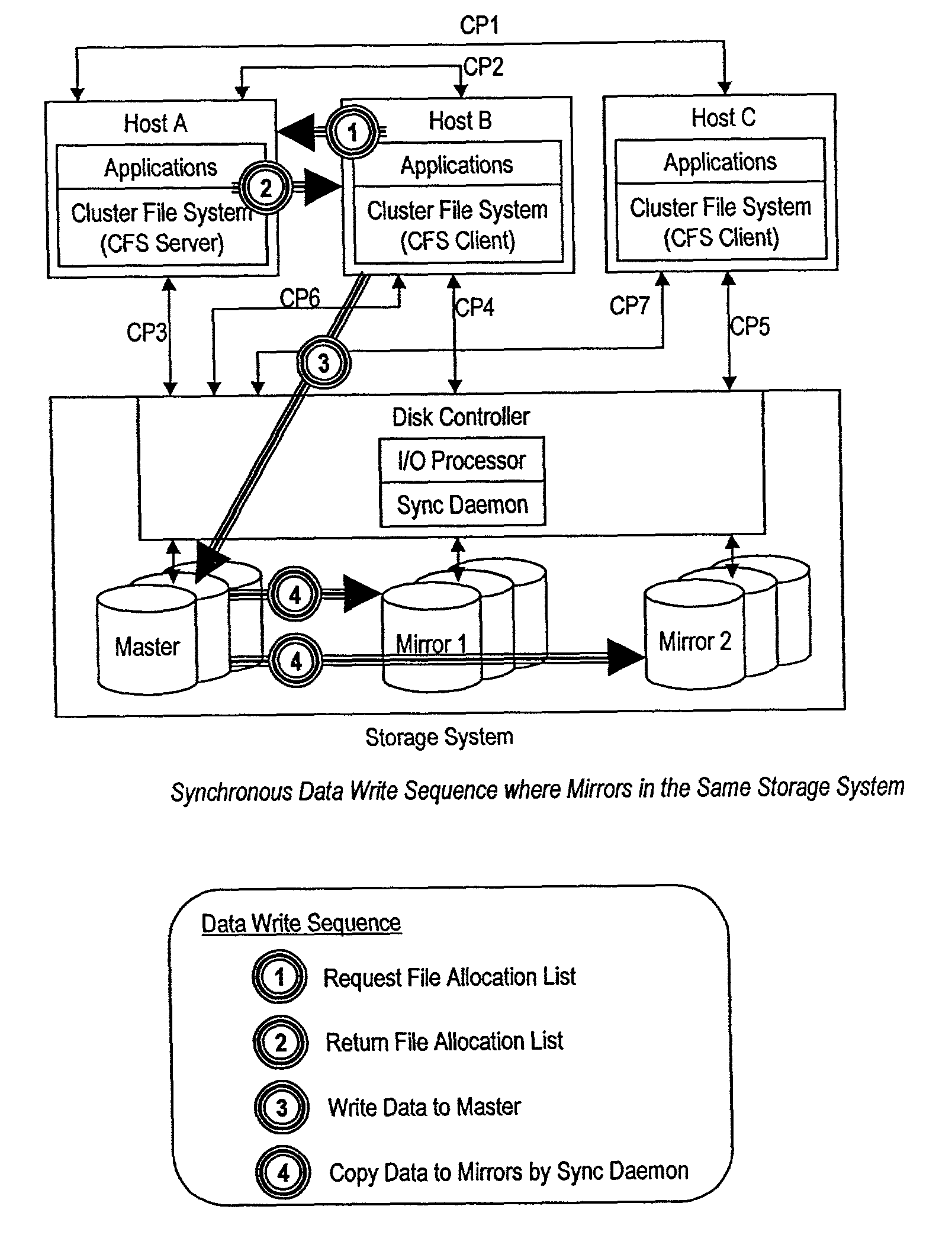
[0022]The present invention offers a number of advantages. For example, one advantage is that storage systems can accomplish data mirroring by themselves without LVMS support. When a disk controller in the storage system receives a data-write request from a host computer, the disk controller issues the same data-write request to different mirrored disk drives in the same pair. It is not limited to whether the disk drives are in the same storage system or in different storage systems. Therefore, CPU load of host computers can be reduced.
[0023]Another advantage is that a cluster file system is introduced to share files among host computers and one dedicated server aggregates disk I / O usage of mirrored disk drives in each pair and tells other host computers which mirrored disk drives the host computers should use thereby balancing the I / O load. This prevents the situation where multiple host computers concurrently utilize the same storage system or the same disk drive at the same time. Other advantages and benefits will become apparent upon studying the disclosure provided hereinbelow.

Problems solved by technology

Consequently, sending video data is often a time-consuming process.
It is, therefore, inefficient to have only one video server handle sending of video data to multiple hosts.
As mentioned above, the size of video data is usually large.
Consequently, if a copy of the video data is to be stored on the local disk drive of each video server, a lot of disk capacity is required for each video server and the associated costs for maintaining the needed disk capacity on each video server are also quite high.
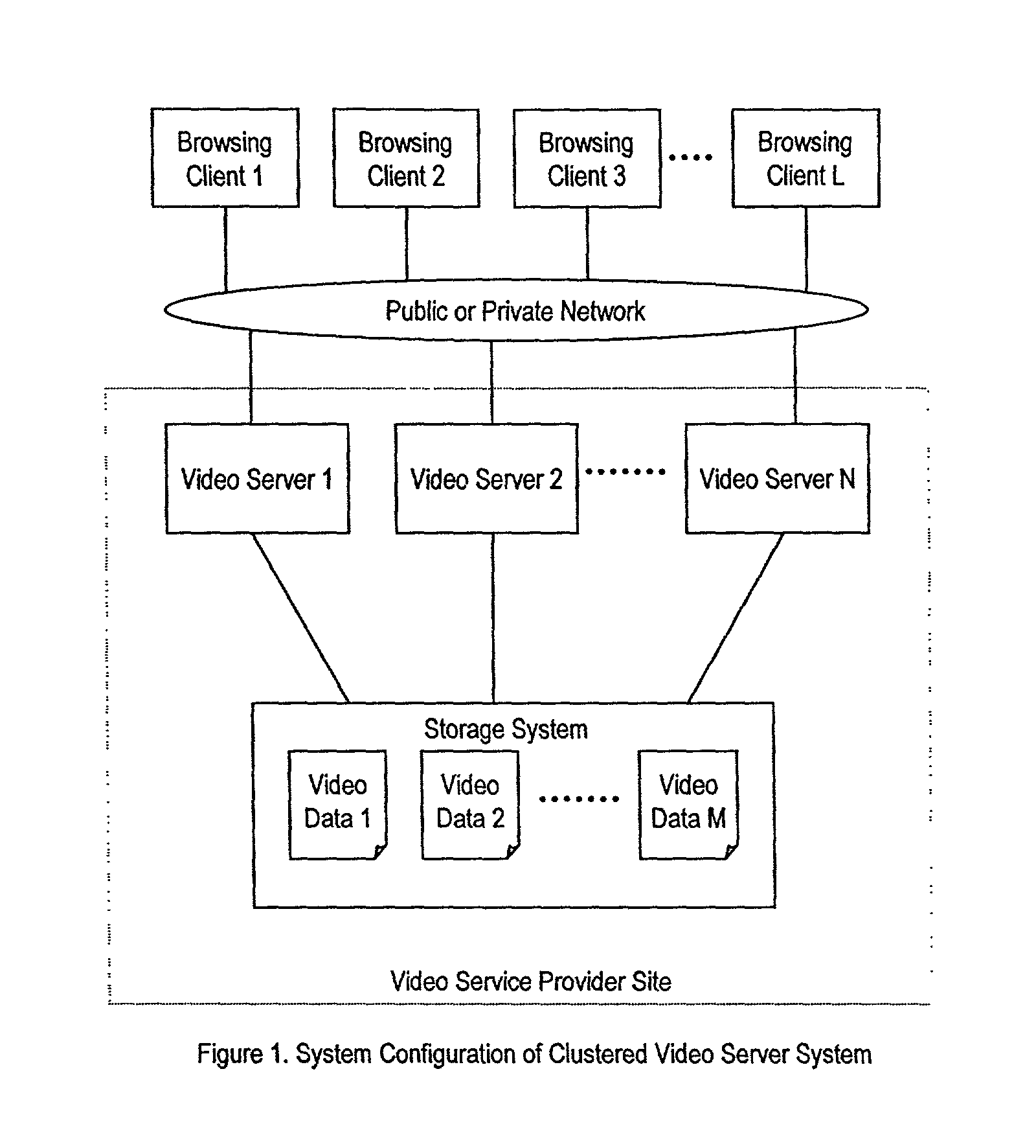
The single storage system, as shown in FIG. 1, suffers from at least four problems, namely, (1) performance bottleneck caused by storing video data in a single storage system, (2) performance bottleneck caused by storing video data on a single disk drive, (3) a single point of failure caused by storing video data in a single storage system, and (4) a single point of failure caused by storing video data on a single disk drive.
For example, one performance bottleneck is the finite I / O throughput of the storage system.
Thus, as the number of browsing clients continues to increase, the I / O throughput of the storage system will at some point reach a maximum level thereby leaving the demands of some clients unfulfilled.
Another performance bottleneck resides inside of the storage system.
Hence, a single disk drive may be a performance bottleneck of the video server system if the same video data stored on that single disk drive are requested by various browsing clients at the same time.
From the system availability point of view, it is clear that the single storage system presents a single point of failure.
If a problem disables the single storage system, then no video data from that system will be available.
Similarly, storing video data on a single disk drive also presents a single point of failure.
However, RAID in the storage system approach cannot be used to solve the problems of a performance bottleneck and a single point of failure caused by storing data in a single storage system.
This is because RAID is limited to configuration within a single storage system itself.
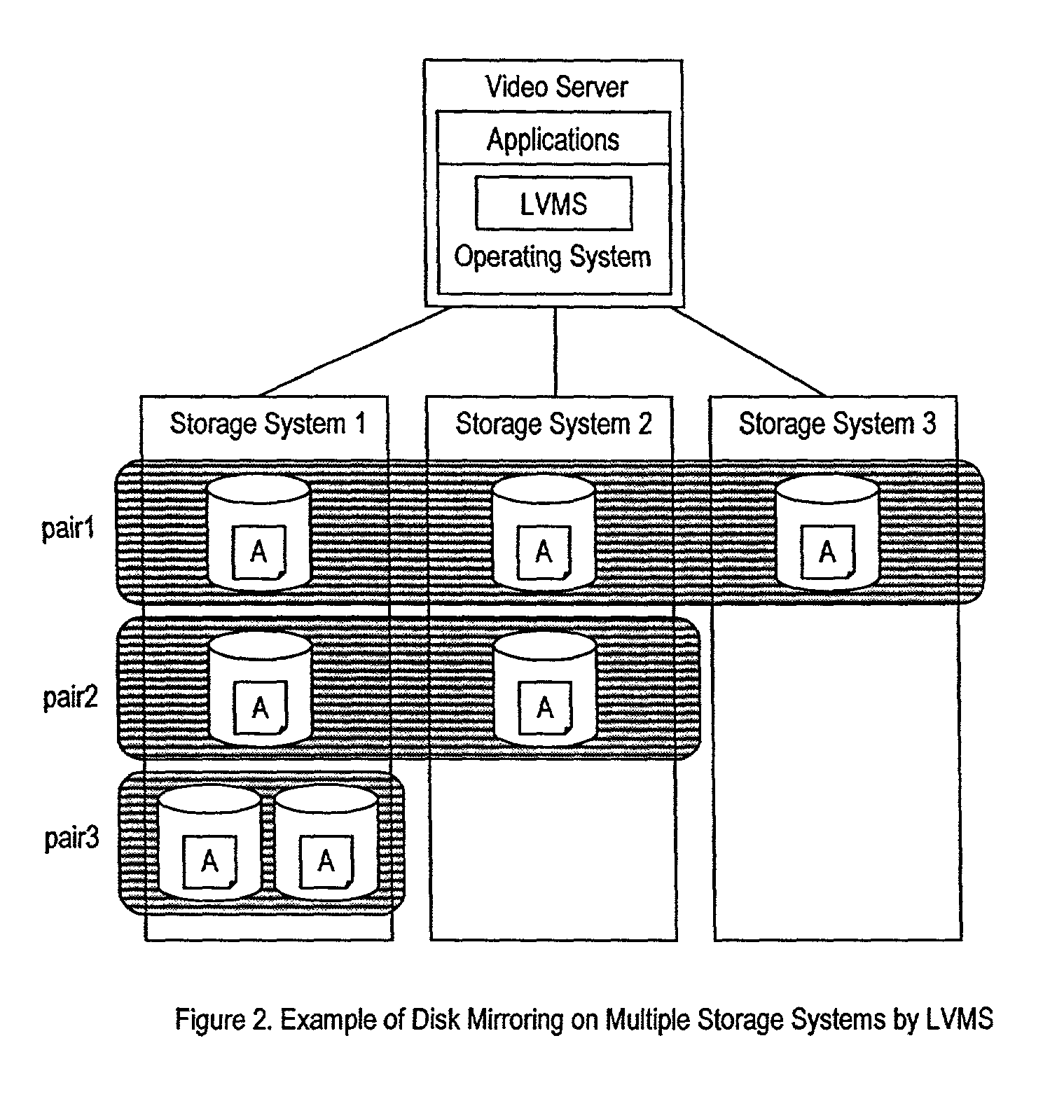
However, LVMS has two major problems.
One of the problems is that issuing multiple data-write requests to storage systems causes a large CPU load on the host computers.
Another problem associated with LVMS is that there is no mechanism to distribute I / O requests among the multiple storage systems.

Method used


Image

  • File sharing system with data mirroring by storage systems
  • File sharing system with data mirroring by storage systems
  • File sharing system with data mirroring by storage systems

Examples


Embodiment Construction

[0064]Various embodiments of the present invention will now be described. FIG. 3 and FIG. 4 are simplified schematic diagrams illustrating two exemplary embodiments of a system 10 in accordance with the present invention. FIG. 3 illustrates a first exemplary embodiment of the system 10 which includes a single storage system 12. FIG. 4 illustrates a second exemplary of the system 10 which includes multiple storage systems 14a, 14b and 14c. Referring to FIGS. 3 and 4, the system 10 further includes multiple host computers 16a, 16b and 16c.

[0065]Focusing on FIG. 3, each host computer 16 further includes one or more applications 18 and a cluster file system 20. The applications 18 may include, for example, a video server running on the host computer 16. The applications 18 may retrieve data through the cluster file system 20. The cluster file system 20 typically resides in the operating system of the host computer 16.

[0066]One of the functions of the cluster file system 20 is to coordi...


PUM


Abstract

A system for optimizing data access is provided. The system includes a cluster file system server, a number of cluster file system clients, and a storage system. The storage system includes disk drives organized as paired master disk drive and one or more mirrored disk drives having copies of the data stored on the master disk drive. When a file is needed, the server determines which pair has the needed file, and then determines which disk drive within the pair should be accessed. The determination is made to balance the access load within the pair, and can select to retrieve the file from the drive which is least frequently accessed. The identification of the disk drive to be accessed is then forwarded to the client thereby allowing the client to access the appropriate disk drive to retrieve the file.

Description

CROSS-REFERENCES TO RELATED APPLICATIONS[0001]This is a continuation-in-part application from commonly assigned U.S. patent application Ser. No. 09 / 606,403, filed on Jun. 30, 2000 now U.S. Pat. No. 7,188,157, entitled “Continuous Update of Data in a Data Server System” by Kodama et al., and U.S. patent application Ser. No. 09 / 815,494, filed on Mar. 21, 2001 now U.S. Pat. No. 6,542,962, entitled “Multiple Processor Data Processing System With Mirrored Data for Distributed Access” by Kodama et al., the disclosures of which are hereby incorporated by reference in their entirety for all purposes.BACKGROUND OF THE INVENTION[0002]The present invention generally relates to file storage systems. More specifically, the present invention relates to a system and method for optimizing data access pertaining to a file sharing system with data mirroring by file storage systems.[0003]Generally, a file storage system contains many files which are concurrently accessible to many hosts or clients. Ma...

Claims


Application Information

Patent Timeline
IPC IPC(8): G06F15/16G06F15/167G06F17/30H04L29/06H04L29/08
CPCH04L29/06H04L67/1008H04L2029/06054Y10S707/99955H04L67/1002Y10S707/99953H04L67/10015H04L67/1001H04L9/40
Inventor KODAMA
Owner HITACHI LTD
Learn More