Multi-layered flexible tube

a flexible tube and multi-layer technology, applied in the field of multi-layer flexible tubes, can solve the problems of reduced production rate, specialized machinery, and large amount of critical space required for reinforcement, and achieve the effects of reducing complexity and production costs of hoses, reducing the complexity of extrusion runs, and remarkably increasing the production rate of coolant hoses

Inactive Publication Date: 2007-10-16
FLUID ROUTING SOLUTIONS
View PDF41 Cites 41 Cited by
  • Summary
  • Abstract
  • Description
  • Claims
  • Application Information

AI Technical Summary

Benefits of technology

[0007]In accordance with one aspect of the present invention, a multi-layered coolant tube having improved hoop strength when compared to previous hoses and which still meets the current requirements of the automotive industry is constructed from at least two, preferably three separate layers of a polymeric material. The layers of polymeric material comprise a first polymeric tubular structure, a second foamed, reinforcement-containing polymeric material adjacent the outer surface of the first polymeric tubular structure and, preferably a third polymeric cover adjacent the outer surface of the reinforcement-containing polymeric layer. Any suitable polymeric material such as thermoplastic polymers, thermoplastic vulcanizates, and elastomeric polymers may be used in forming any or all of the various layers of the multi-tubular hose.
[0011]Each of the first tubular structure, the intermediate reinforcement layer and the cover layer may be formed from the same or from different polymeric materials. The intermediate polymeric material is generally distinguished from the first and third polymeric layers, in that the intermediate polymeric material is a foamed material containing a plurality of reinforcing elements in the form of short or long fibers or elements. The intermediate reinforcement layer preferably contains an adhesive material such as modified polypropylene, e.g., maleated polypropylene available from Atofina, in a sufficient amount to enhance the adherence o the intermediate polymeric material to the reinforcement fibers.
[0013]In accordance with another aspect of the invention, a method for manufacturing the coolant hose of the present invention comprises extruding the polymeric materials to form the multi-layered coolant hose. The various layers of polymeric material may be extruded simultaneously through the same extruder head or sequentially through different extruder heads. Preferably, the various layers are extruded at the same time in the same head. It has been found that, by extruding the various layers through a single extruder head without the need for additional stations, the production rate of the coolant hose is remarkably increased and the length of the extrusion runs become virtually unlimited, thereby significantly decreasing the complexity and the production costs of the hose.

Problems solved by technology

The application of the reinforcement greatly increases the complexity of the manufacture process by requiring a separate manufacturing step wherein the inner tubular structure of the hose is cooled in order to apply the reinforcing material and then heated up again before extruding any subsequent layers, resulting in decreased production rates.
Furthermore, specialized machinery, which takes up a considerable amount of critical space, is required to apply the reinforcement.

Method used


Image

  • Multi-layered flexible tube
  • Multi-layered flexible tube
  • Multi-layered flexible tube

Examples


Embodiment Construction

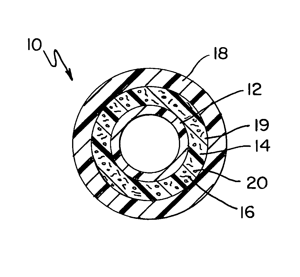
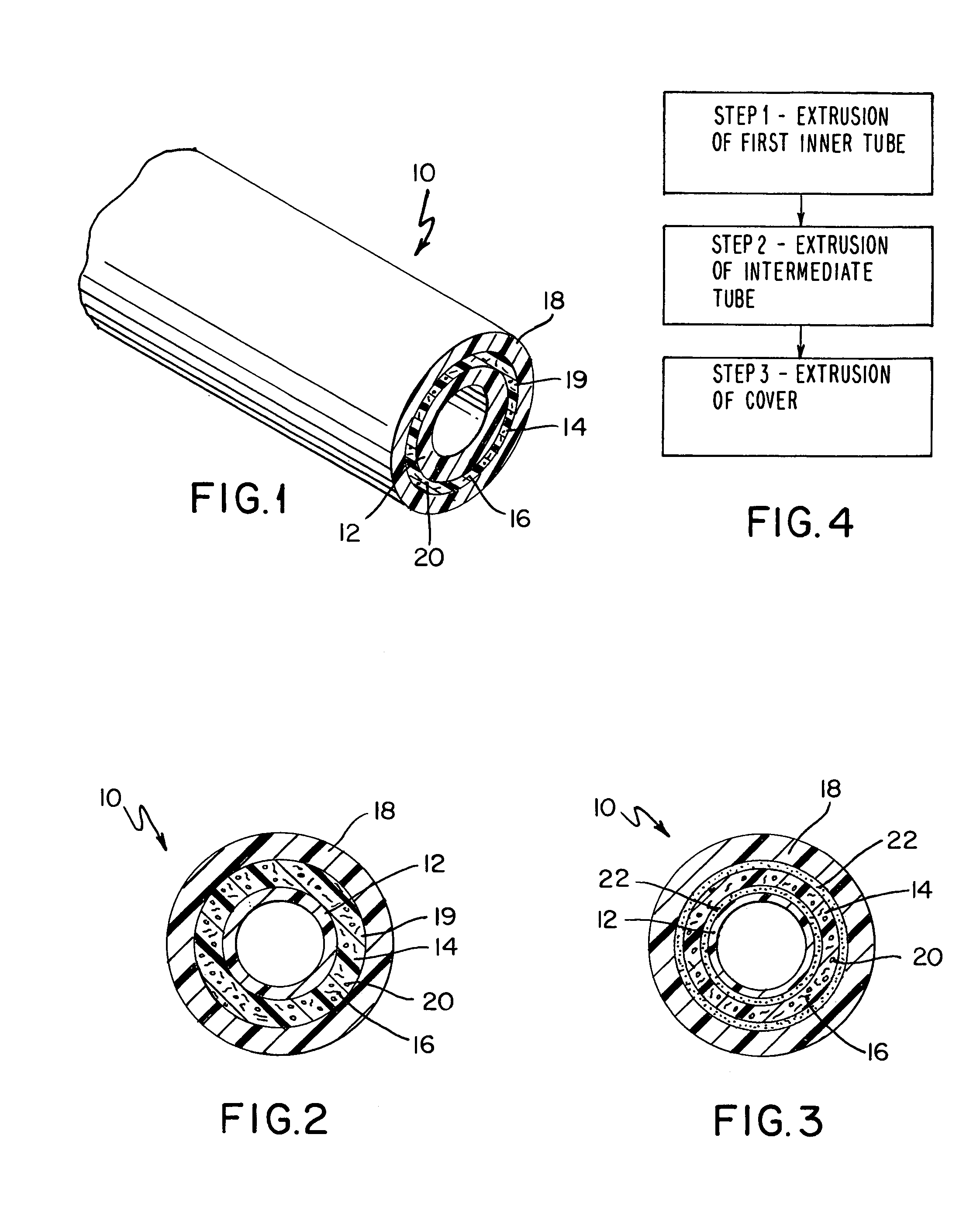
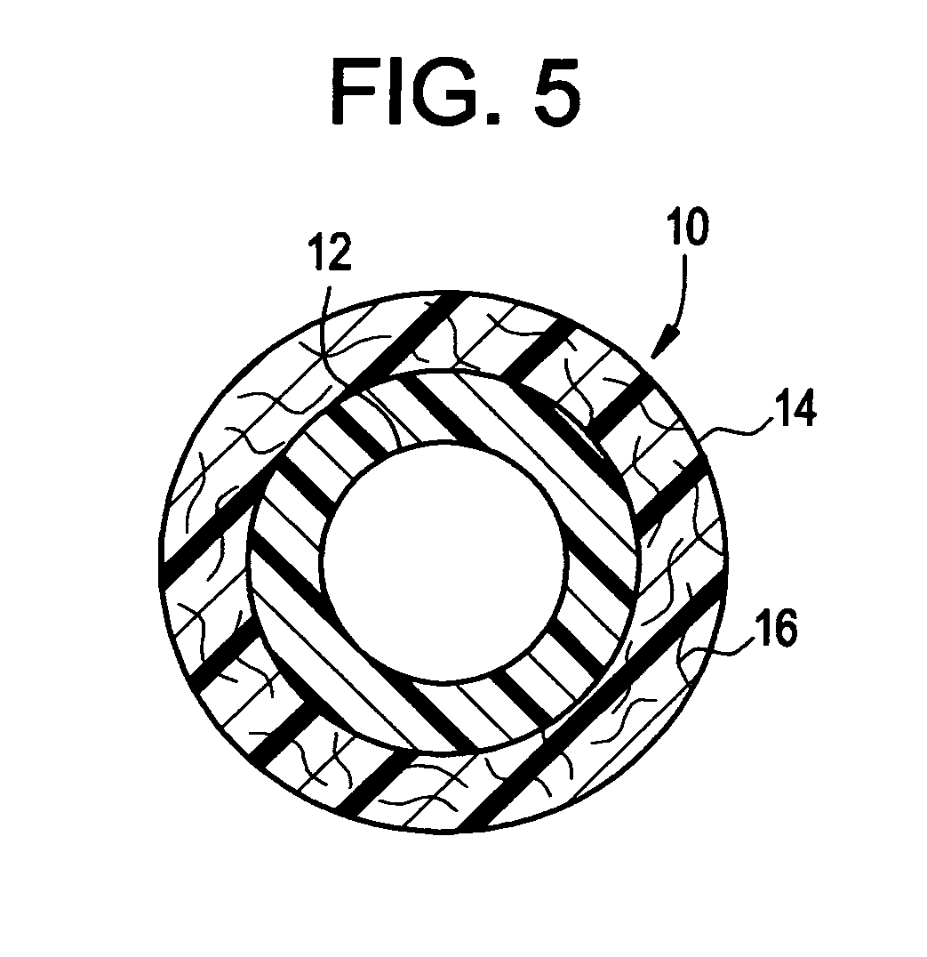
[0019]The present coolant hose is a multi-layered construction comprising a first tubular structure having an inner surface and an outer surface; a second polymeric tubular structure having an inner surface and an outer surface wherein the inner surface of the second tubular structure is adhered to the outer surface of the first tubular structure; and a third polymeric tubular structure having an inner surface and an outer surface wherein the inner surface of the third tubular structure is adhered to the outer surface of the second tubular structure. In accordance with the present invention, the second tubular structure, which is intermediate the first tubular structure, and the third tubular structure, is a foamable tubular structure which further comprises a plurality of reinforcement elements in the form of short fibers dispersed therein. It has been found that if the short reinforcement elements are incorporated into a foamable polymeric composition, the foaming action during ex...


PUM

PropertyMeasurementUnit
diameteraaaaaaaaaa
lengthaaaaaaaaaa
diameteraaaaaaaaaa

Abstract

A multi-layered tube comprising a first inner polymeric tubular structure, a second foamed polymeric structure containing a plurality of short or long reinforcing elements dispersed therein and, optionally, a third cover layer on the outer surface of the reinforcing layer; and a method for manufacturing the multi-layered hose are disclosed.

Description

RELATED APPLICATION[0001]Filed concurrently with this application is U.S. Ser. No. 10 / 770,071 to Cleveland et al. entitled “Multi-Layered Hose”.BACKGROUND OF THE INVENTION[0002]Multiple layered hoses including hoses, which contain foamed and non-foamed layers, are known in the art. For example, U.S. Pat No. 4,644,977 to Arterburn discloses a reinforced lightweight, flexible hose which comprises a two-component tube consisting of a thin, non-foamed inner liner and a foamed interlayer circumferentially encompassing the inner liner; a separate of textile reinforcement telescoped over the two-component tube; and a two-component, coextruded, thermoplastic outer cover layer circumferentially encompassing the reinforced tube, wherein the two-component coextruded thermoplastic outer cover includes a first thermoplastic layer with a multitude of closed gas-filled cells and a second thermoplastic layer which is non-foamed. The second, non-foamed thermoplastic layer has a thickness of from 15%...

Claims


Application Information

Patent Timeline
Patent Type & Authority Patents(United States)
IPC IPC(8): F16L11/00B32B1/08F16L11/10
CPCB32B1/08F16L11/10Y10T428/1372Y10T428/1393B32B27/065B32B37/15B32B2307/738B32B27/24B32B2597/00B32B2305/08
Inventor CLEVELAND, RAFAEL L.DAVIS, ANDREW R.
Owner FLUID ROUTING SOLUTIONS
Why Eureka
Try Eureka