Mounting fitting

a technology for mounting fittings and fittings, applied in the direction of cable arrangements between relatively moving parts, coupling device connections, curtain suspension devices, etc., can solve problems such as insufficient design strength, and achieve the effect of improving the strength of mounting fittings

Inactive Publication Date: 2007-10-16
SUMITOMO WIRING SYST LTD
View PDF11 Cites 20 Cited by
  • Summary
  • Abstract
  • Description
  • Claims
  • Application Information

AI Technical Summary

Benefits of technology

[0008]The invention relates to a mounting fitting formed by bending a metallic plate material and used to make an object, such as a casing for accommodating wiring for a sliding door that is to be mounted fixedly to a fixed member, such as a panel. The mounting fitting has first and second mounting panels that are displaced from one another. The first mounting panel is for opposing and mounting on the object to be mounted. The second mounting panel is for opposing and mounting on the fixed member. Reinforcing flanges are bent so that edge ends thereof face substantially in the same direction and on the same side along the longitudinal direction thereof. The reinforcing flanges are at the opposite lateral edges extending from the first mounting panel to the second mounting panel and are substantially continuous along the longitudinal direction without any cut. Thus, the strength of the mounting fitting is improved as compared to conventional ones.
[0009]The reinforcing flanges preferably are formed at the opposite lateral edges extending from the first mounting panel to the second mounting panel and at least ends of the lateral edges at one side are connected by a U-shaped curved portion. Accordingly, a long range is ensured for the continuous reinforcing flange and reinforcement is improved.

Problems solved by technology

A problem arises if both surfaces of the fitting are mounting surfaces.
This design may not be sufficiently strong.

Method used


Image

  • Mounting fitting
  • Mounting fitting
  • Mounting fitting

Examples


Embodiment Construction

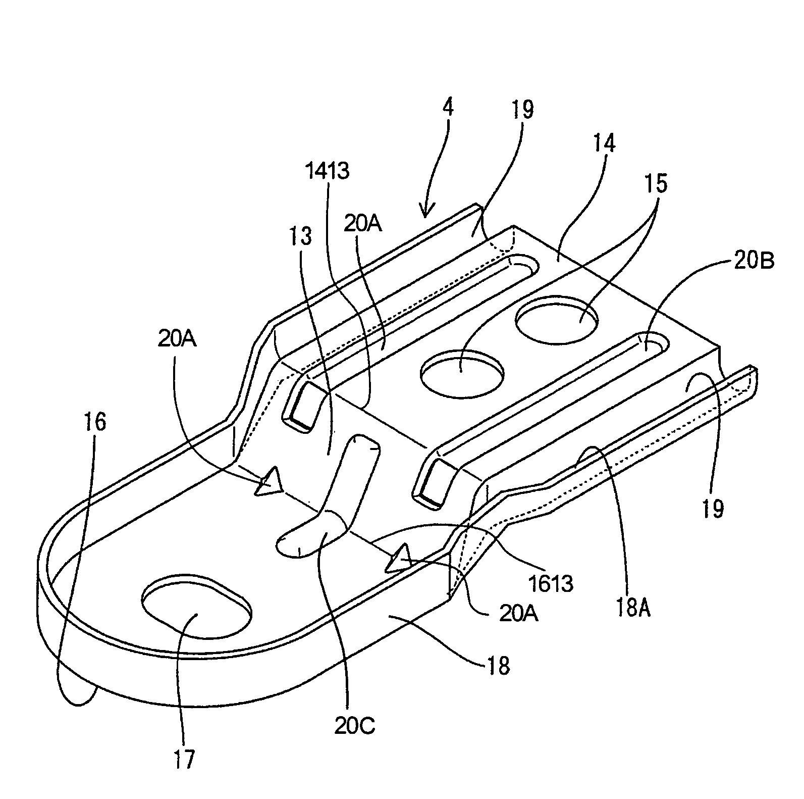
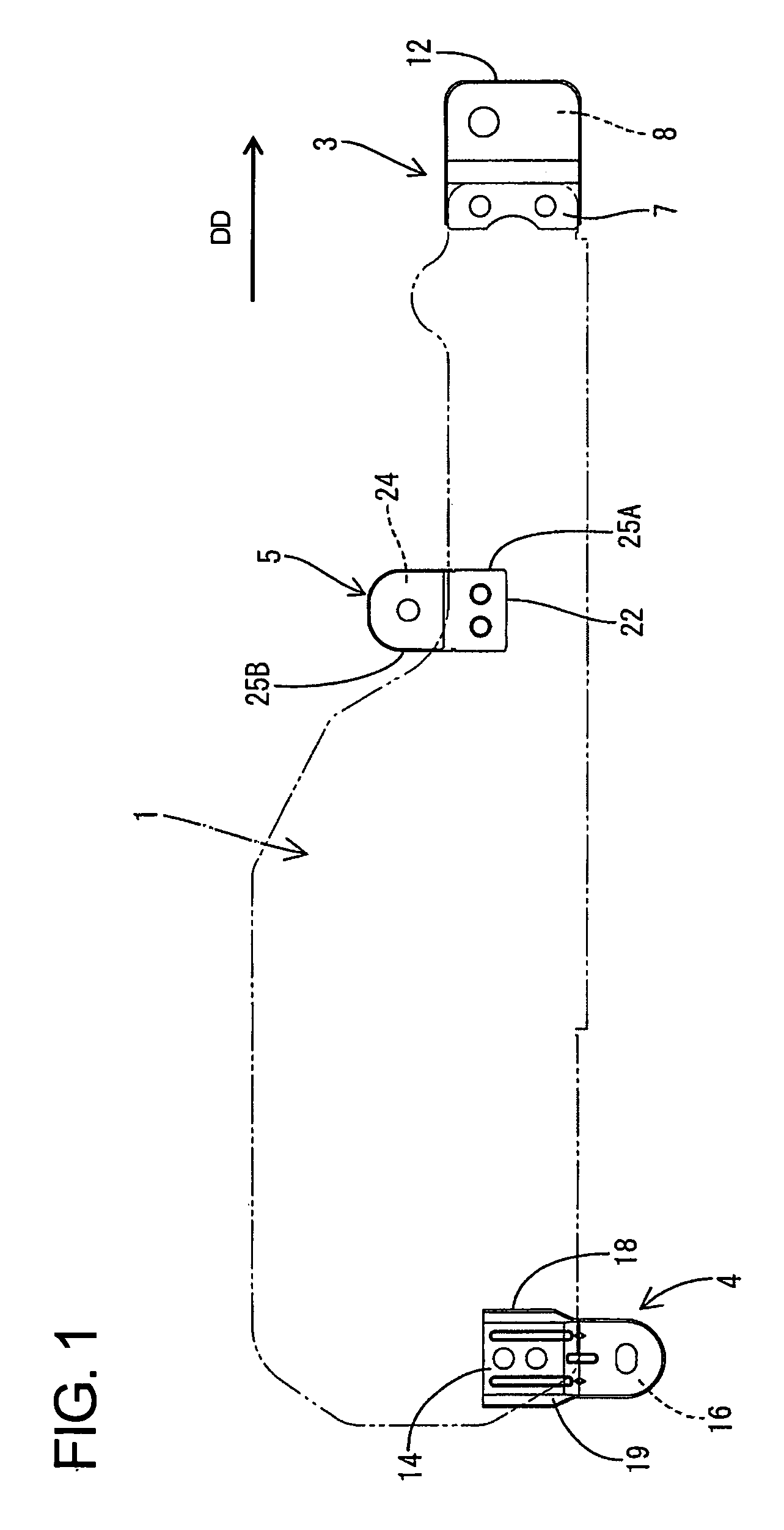
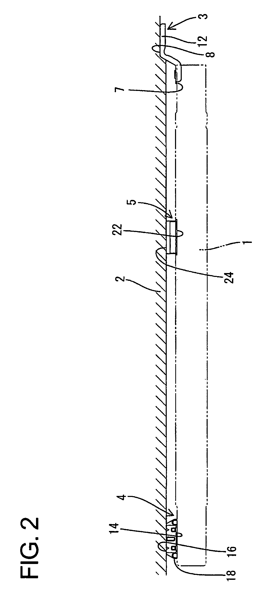
[0024]Mounting fittings according to the invention are used for a power feeding device for a slide door of an automotive vehicle. Specifically, wiring for feeding power to electrical components of the door must be laid between the slide door of the automotive vehicle and a vehicle body. Thus, a casing 1 for accommodating the wiring for the door is incorporated into the door. The casing 1 has two long opposed plates made of a metal (aluminum alloy) and / or of a composite material, and wires, connectors, electric circuits and the like are accommodated in a space between the plates. Connectors are joined with ends of the wires and are electrically connectable with electrical components (e.g. a motor for moving a door glass up and down) in the door. The casing 1 is fixed to a lower part of a door inner panel 2 by mounting fittings preferably made of the same material as the casing 1.

[0025]The casing 1 receives a relatively large force, such as a pulling force, from a wire laying portion ...


PUM


Abstract

A mounting fitting (3, 5) is made of a metallic plate material, wherein a first mounting panel (7, 14) to be mounted on a casing (1) is defined on one surface, and a second mounting panel (8, 16) to be mounted on an inner panel (2) is defined on the opposite surface. A reinforcing edge (12, 18) is formed by bending at a peripheral edge portion of the mounting fitting (3, 5) such that an edge end thereof faces in the same direction. The reinforcing edge (12, 18) is continuous along the longitudinal direction thereof without any cut.

Description

BACKGROUND OF THE INVENTION[0001]1. Field of the Invention[0002]The present invention relates to a mounting fitting.[0003]2. Description of the Related Art[0004]Japanese Unexamined Patent Publication No. 2003-232084 discloses a metallic mounting fitting for fixing an object to a fixed member. The mounting fittings are formed by press-working metallic plate materials and often must have a high strength. Strength can be enhanced by bending or embossing the metallic plate to form a reinforcement.[0005]The fitting is bent at about 90°, and two objects are mounted fixed at the opposite ends. A reinforcing rib extends over substantially the entire length of one surface to achieve a high strength. However, the reinforcing rib can be formed over the entire length in this way only because the surfaces of the fitting that will be fixed to the objects are on only one surface of the fitting. A problem arises if both surfaces of the fitting are mounting surfaces.[0006]FIG. 5 shows a fitting 5 wi...

Claims


Application Information

Patent Timeline
Patent Type & Authority Patents(United States)
IPC IPC(8): A47F5/00
CPCB60J5/06H02G11/00Y10S248/903
Inventor KIDA, YUJIKOBAYASHI, YOSHINAO
Owner SUMITOMO WIRING SYST LTD
Why Eureka
Try Eureka