Surface lighting device

a liquid crystal display and surface lighting technology, applied in semiconductor devices, lighting and heating apparatus, instruments, etc., can solve the problems of narrow color reproducibility range, large display area, and inability to achieve high luminan

Active Publication Date: 2007-10-16
SHARP KK
View PDF36 Cites 66 Cited by
  • Summary
  • Abstract
  • Description
  • Claims
  • Application Information

AI Technical Summary

Problems solved by technology

However, the cold cathode tube has problems in that high voltage is required for an inverter and that mercury is contained and, to make matters worse, has a problem in that a color reproduction range is narrow.
In the display device 160 of the conventional example 1, since LEDs are arranged at corners or sides of a light guide plate, there is a problem in that high luminance cannot be attained on a large display area.
In addition, in the liquid crystal display device 170 of the conventional example 2, white LEDs are used, but the white LEDs have a problem in that the range of color reproducibility is narrow, since the white is made by emitting blue color light from blue LCD to a yellow fluorescent material.
Moreover, in the surface lighting of the liquid crystal display 180 of the conventional example 3, since LEDs of different colors are used, there is a problem in that unevenness of colors and unevenness of luminance due to unbalance of amounts of light among the LEDs, which emit light of different colors, cannot be overcome easily.

Method used


Image

  • Surface lighting device
  • Surface lighting device
  • Surface lighting device

Examples


first embodiment

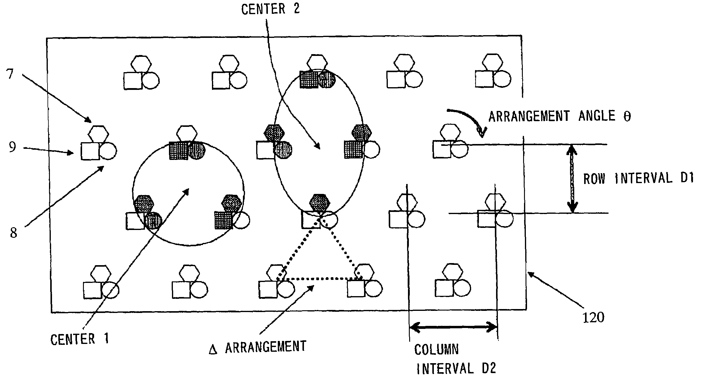
[0109]According to the first and the second aspects of the present invention, as described in the first embodiment, a substrate surface cover rate by a reflection plate can be increased and, even in the case in which white light is used for a backlight unit, a surface lighting device with unevenness of luminance prevented can be provided.

[0110]In addition, according to the third and the fourth aspects of the present invention, as described in the second to the fourth embodiments, even in the case in which white light is used for a backlight unit, a surface lighting device with unevenness of color prevented can be provided.

fourth embodiment

[0111]Moreover, according to the fifth aspect of the present invention, as described in the fourth embodiment, although white light is used for a backlight unit, a liquid crystal display device, which incorporates a surface lighting device with unevenness of color or unevenness of luminance prevented, can be provided.


PUM

PropertyMeasurementUnit
angleaaaaaaaaaa
widthaaaaaaaaaa
widthaaaaaaaaaa

Abstract

A surface lighting device including, a surface light source in which light-emitting element groups having three light-emitting elements, which correspond to three primary colors of light, arranged to be continguous with vertexes of a triangle are arranged in a matrix shape; a substrate on which the light-emitting element groups are arranged; and a diffusion plate which is located above the surface light source. the light-emitting element groups are arranged to be deviated every other column or row such that a positional relation among the light-emitting element groups is a delta shape. Additionally, a row interval, a column interval, and an arrangement angle of the light-emitting element groups are adjusted such that, when it is assumed that an average amount of light calculated from a sum of amounts of light of the respective single color light-emitting elements at a center of gravity of the delta shape and a center of gravity of a diamond shape formed by two delta shapes is between 75% and 125%.

Description

BACKGROUND OF THE INVENTION[0001]1. Field of the Invention[0002]The present invention relates to a surface lighting device and a liquid crystal display device including the surface lighting device, and in particular to the surface lighting device which realizes a surface light source by arranging LEDs (Light Emitting Diode), which are capable of emitting light of primary colors of red, green and blue, or LEDs, which emit light of two or more kinds of colors in a complementary color relation, and the liquid crystal display device which attains high luminance even on a large display area by including the surface lighting device.[0003]2. Description of the Related Art[0004]Examples of a backlight unit incorporated in a liquid crystal display device include a sidelight or direct type backlight unit using a cold cathode tube and a sidelight type backlight unit using an LED. However, the cold cathode tube has problems in that high voltage is required for an inverter and that mercury is co...

Claims


Application Information

Patent Timeline
Patent Type & Authority Patents(United States)
IPC IPC(8): F21V9/00F21V23/04G09F13/04F21V7/04F21V29/00G02F1/133G02F1/13357H01L33/00H01L33/48
CPCG02F1/133603G02F1/133605G02F1/133609F21Y2105/005G02F2001/133613Y10S362/80G02F1/133611F21Y2107/50F21Y2115/10G02F1/133613E03F5/101E03F5/107E03F5/14
Inventor SUZUKI, TOSHIHIRO
Owner SHARP KK
Why Eureka
Try Eureka