Decontamination device

Active Publication Date: 2007-10-16
LAKE JR ROBERT F +1
View PDF5 Cites 155 Cited by
  • Summary
  • Abstract
  • Description
  • Claims
  • Application Information

AI Technical Summary

Benefits of technology

[0007]The decontamination device can have structure for attaching the decontamination device to the medical apparatus when the medical apparat

Problems solved by technology

The design, construction, and expense of the device can impede decontamination procedures.
Decontamination of medical apparatus usually requires time con

Method used


Image

  • Decontamination device
  • Decontamination device
  • Decontamination device

Examples


Example

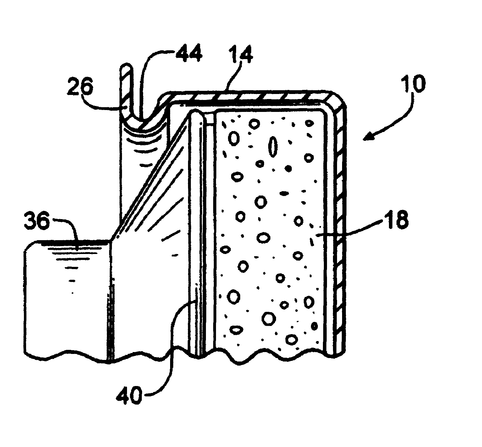
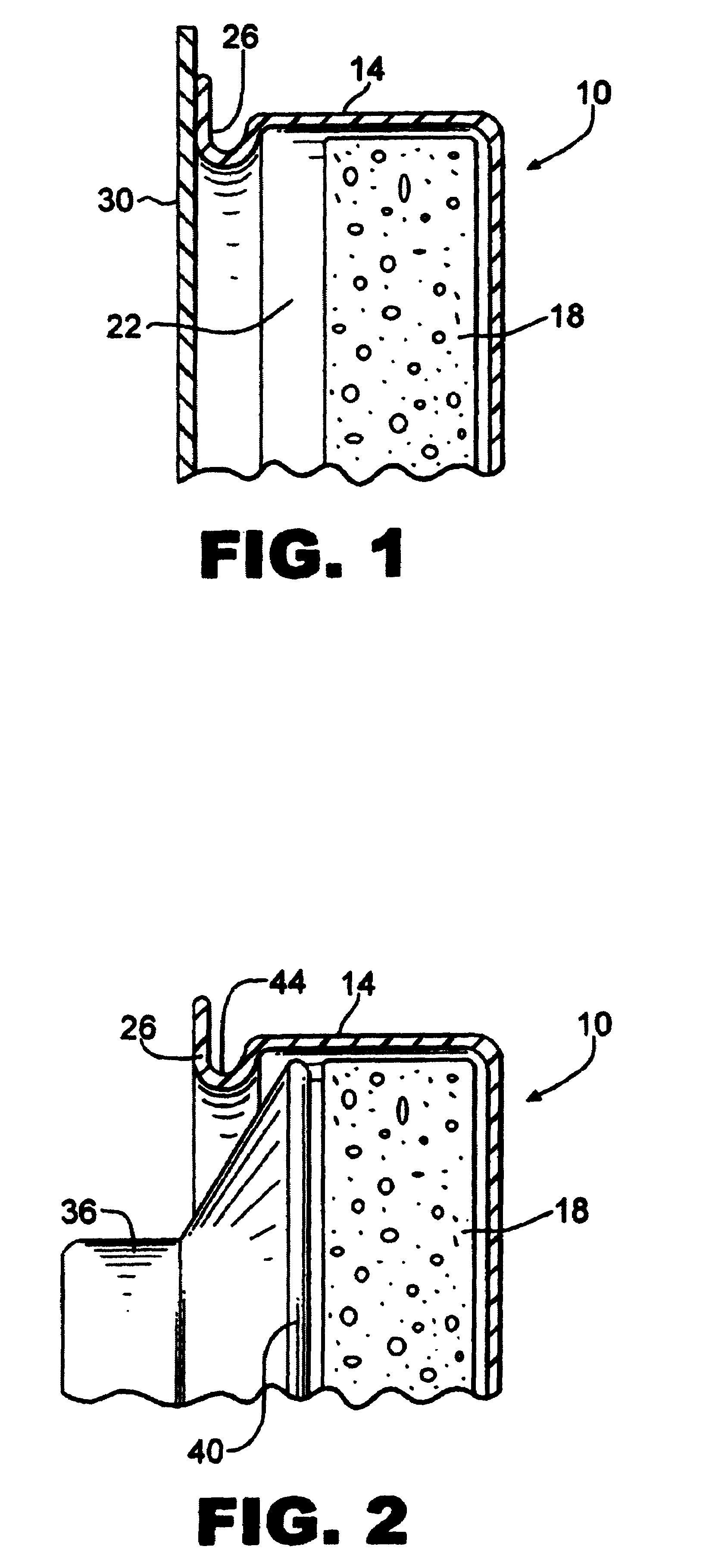
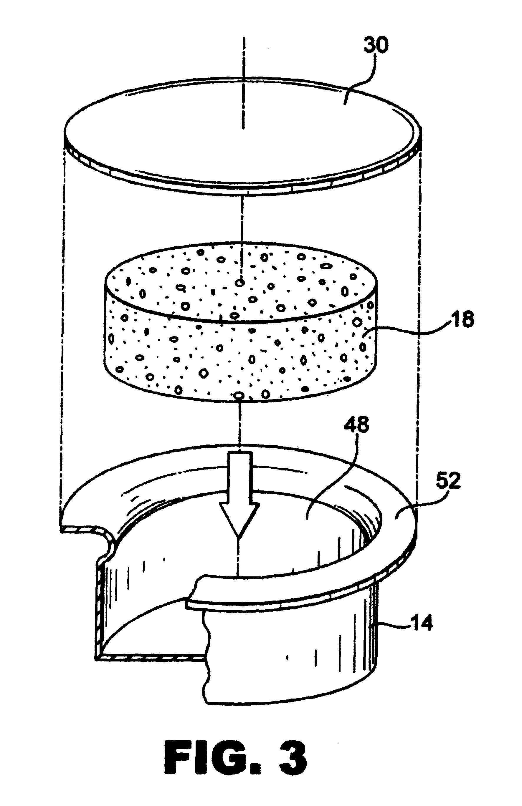
[0022]There is shown is FIG. 1 a decontamination device 10 having a housing 14 and a dispenser 18. The dispenser 18 is provided in an interior 22 formed by the housing 14. Structure 26 is provided for engaging a medical apparatus. A removable cover 30 can be provided to maintain the sterility of the device when not in use, or as packaging prior to initial use.

[0023]The housing 14 is dimensioned to receive a portion of a medical apparatus that is to be decontaminated. The invention can be utilized with many different types of medical apparatus. There is shown in FIG. 2 the head 36 of a stethoscope. The head 36 has a diaphragm 40, and the interior of housing 14 is dimensioned to receive the diaphragm 40 so that it will contact the dispenser 18.

[0024]The dispenser 18 can be of any suitable design for contacting the desired portion of the medical apparatus with the decontaminating compound. In the embodiment shown, the dispenser 18 comprises an absorbent pad which absorbs the decontamin...


PUM


Abstract

A decontamination device for decontaminating medical apparatus includes a housing and a dispenser within the housing for contacting a portion of the medical apparatus with a decontaminating compound when the portion of the medical apparatus is placed within the housing. Structure for removably engaging the housing to the medical apparatus is provided. The decontamination device can be used with many different medical apparatus, such as stethoscopes. A method for decontaminating medical apparatus is also provided.

Description

STATEMENT REGARDING FEDERALLY SPONSORED RESEARCH OR DEVELOPMENT[0001]Not applicable.FIELD OF THE INVENTION[0002]This invention relates generally to medical apparatus and, more particularly, to decontamination devices for medical apparatus.BACKGROUND OF THE INVENTION[0003]The transmission of infectious disease is a matter of increasing concern among healthcare professionals. It has long been known that medical instruments must be decontaminated, in order to prevent the spread of infectious disease among different patients with whom the medical apparatus comes in contact. Decontamination includes the removal of foreign material such as chemical or radiological contaminants, as well as sterilization and disinfection. Sterilization is a form of decontamination in which all forms of microbial life are killed. Disinfection is a relative term meaning that the microbial burden of an instrument is reduced but not eliminated. Some medical apparatus, such as stethoscopes, are decontaminated on...

Claims


Application Information

Patent Timeline
IPC IPC(8): A61L2/00A61L2/18A61L2/26A61L2/28
CPCA61L2/18A61L2/28A61L2202/24A61L2/186A61B7/02
Inventor LAKE, JR., ROBERT F.TENNANT, JEFFREY S.
Owner LAKE JR ROBERT F
Why Eureka
Try Eureka