Tube end forming and coping method and apparatus

a technology of end forming and coping, which is applied in the direction of manufacturing tools, metal rolling, metal rolling, etc., can solve the problems of relatively high fabrication cost and difficult task of header manufacturers, and achieve the effect of eliminating the need for labor-intensive hand forming and easy assembly and welding

Inactive Publication Date: 2007-10-23
KRAUSS ROBERT
View PDF6 Cites 8 Cited by
  • Summary
  • Abstract
  • Description
  • Claims
  • Application Information

AI Technical Summary

Benefits of technology

[0007]This feature provides the ability to form a part for an extremely tight exit from a header flange. This is crucial when designing headers where space constraints are limiting, a difficult task for header manufacturers. As noted above, some of the prior art accomplished this by using a ram to force a die assembly into and over a tube to produce the desired shape using tooling which is relatively expensive to fabricate. The present invention allows an exhaust header manufacturer to pre-form tubular parts for easy assembly and welding, eliminating the need for labor-intensive hand forming.
[0008]The machine process of the present invention provides a new capability of coping a tube end. This feature allows parts to be cut on virtually any angle in a bend for complex tubular assemblies, particularly attractive to race-car chassis builders since designs are constantly changing. The machine is thus capable of a wide variety of tube end-finishing procedures.
[0012](2) Forming and coping tools that are adjusted vertically and angularly using hand screws and locking knobs for rapid set ups.

Problems solved by technology

This is crucial when designing headers where space constraints are limiting, a difficult task for header manufacturers.
As noted above, some of the prior art accomplished this by using a ram to force a die assembly into and over a tube to produce the desired shape using tooling which is relatively expensive to fabricate.

Method used


Image

  • Tube end forming and coping method and apparatus
  • Tube end forming and coping method and apparatus
  • Tube end forming and coping method and apparatus

Examples


Embodiment Construction

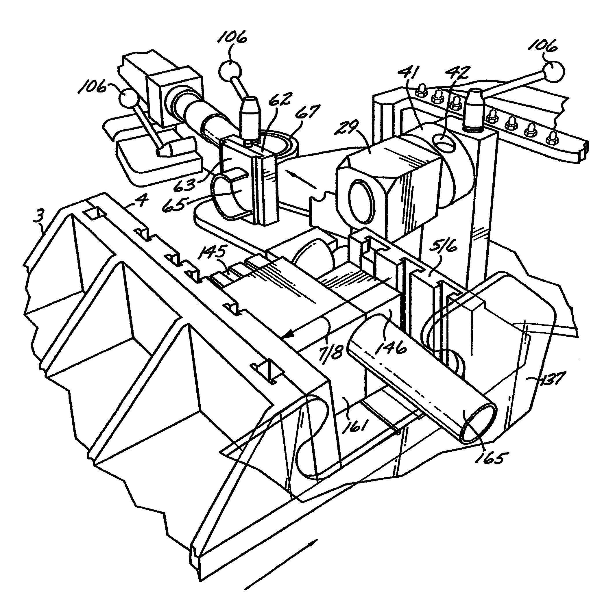
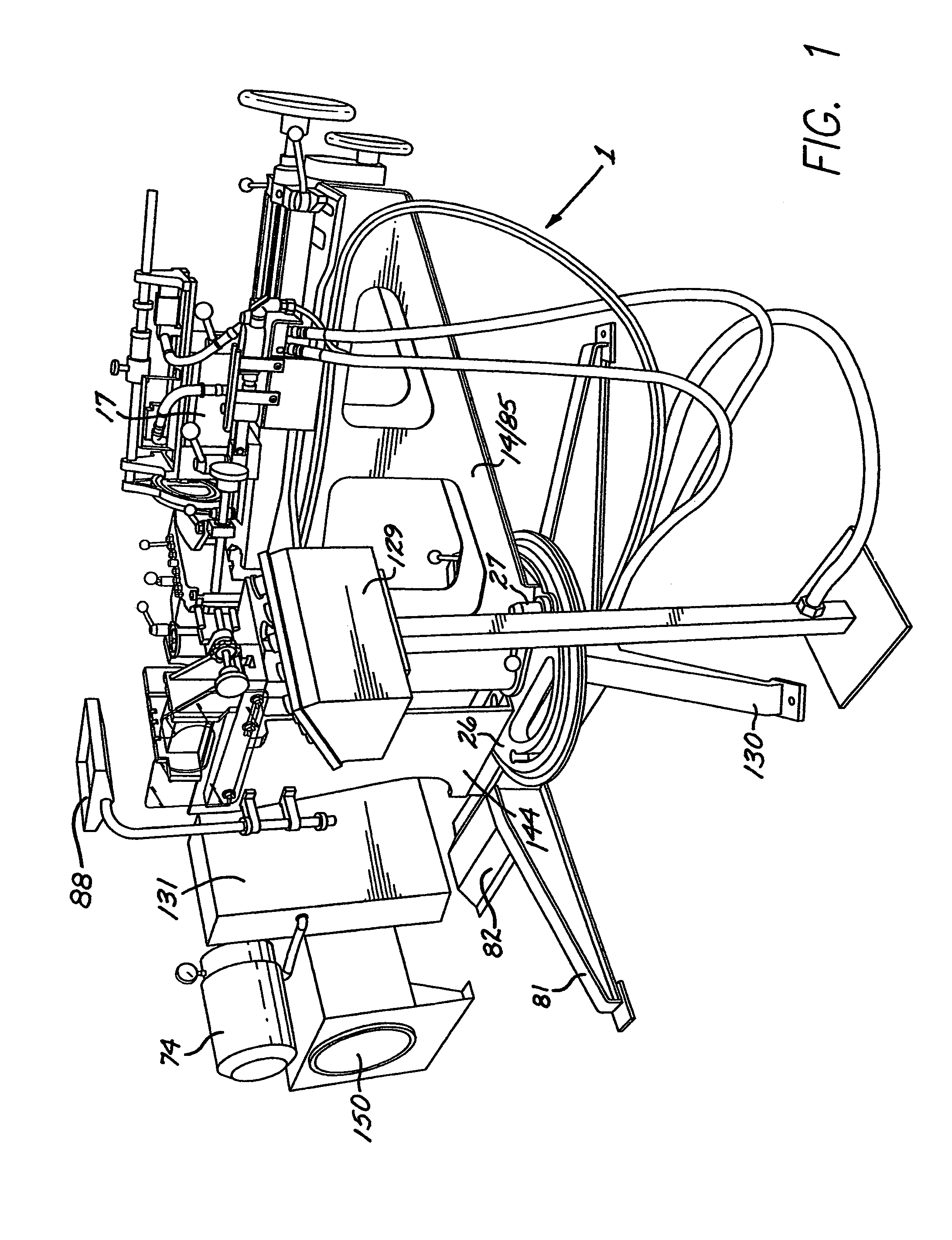
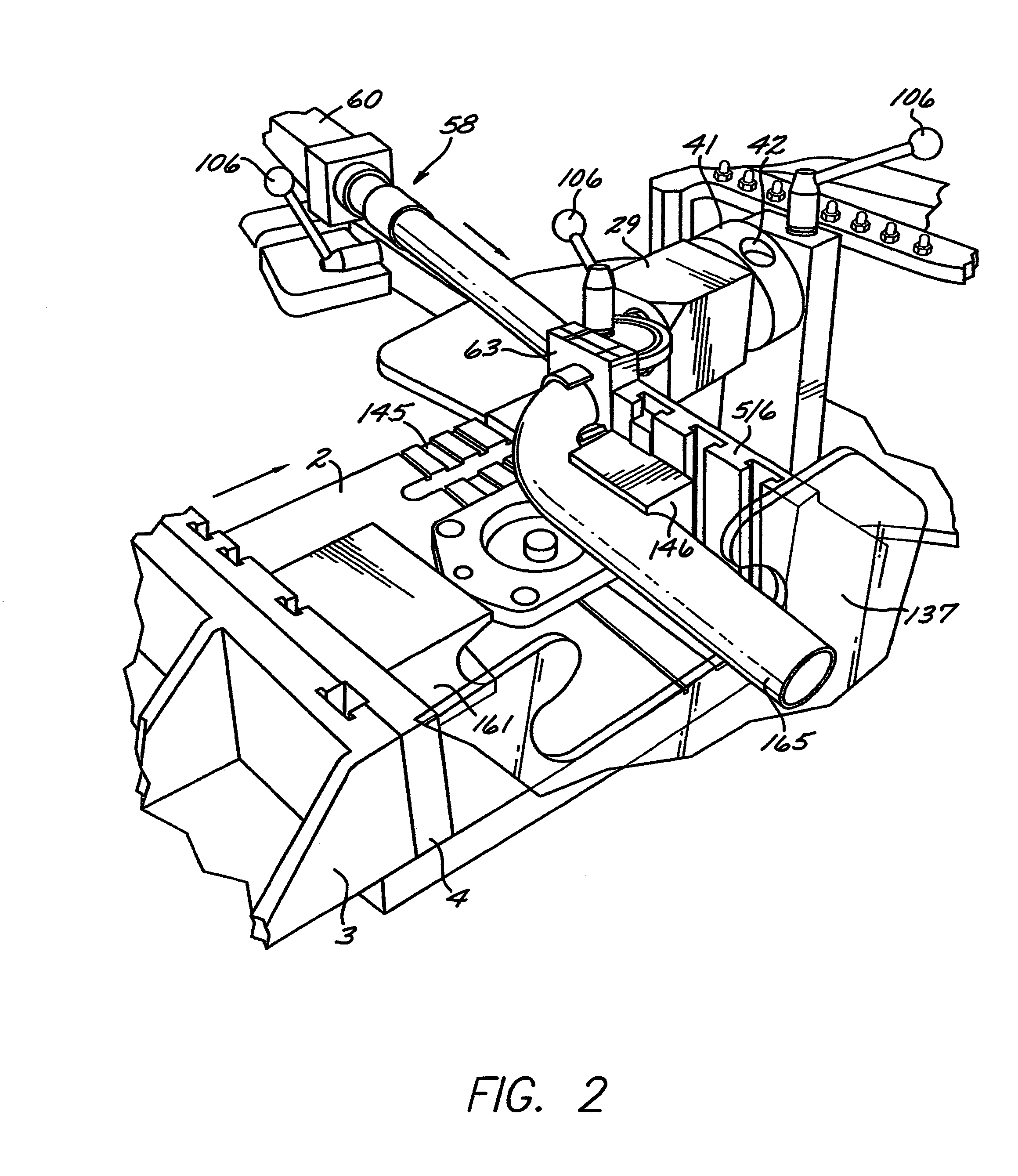
[0073]FIG. 1 is a perspective view of the tube forming apparatus 1 of the invention. Apparatus 1 is designed to be used for an infinite variety of tube end finishing tasks including straight or in bend forming, compound straight or in bend forming, tight exit forming, two step forming, straight or in bend coping. A tube end can be re-shaped to any configuration within its structural limits for a given application. Apparatus 1 has a clamping mechanism which works in conjunction with tube grips 8 to hold an object tube 165 in place for forming. FIG. 2 is a partial perspective view showing tube 165 located in place by tube end locator tool 63 and FIG. 3 is a partial perspective view showing tube 165 held by grippers 8 and locator tool 63 retracted. FIG. 4 illustrates forming tool holder 41 moving inwardly to initiate the forming of end of tube 165. For tubes that require forming in a bend, a specially designed tooling shoe is incorporated to support the bend radius. Once a tube 165 has...


PUM

PropertyMeasurementUnit
angleaaaaaaaaaa
working angleaaaaaaaaaa
radial arm angleaaaaaaaaaa

Abstract

Apparatus for both forming and coping the end of a tube. The tube is gripped such that it is aligned with a movable first tool assembly that is positioned, in a first operation, adjacent said tube end. The tool assembly is then controlled in a manner such that the tube end is formed. Thereafter, the first tool assembly is removed and replaced with a second tool assembly which is controlled in a manner such that the formed tube end is then coped. The movable tool assembly is rotatable about its axis to a predetermined plane.

Description

BACKGROUND OF THE INVENTION[0001]1. Field of the Invention[0002]The present invention provides an apparatus for fabricating tubes and, in particular, apparatus for both forming and coping, or cutting, tube ends on any plane of bend.[0003]2. Description of the Prior Art[0004]Currently there are a wide variety of machines available for straight tube end forming. There are also a number of machines designed for straight tube end coping sch as disclosed in U.S. Pat. No. 5,118,228 to Story. However, a machine that can perform both tasks is currently unavailable. In addition, a machine capable of forming tube ends in the bend section is also not available. Current manufacturers use a wide variety of techniques and tooling to form round tubing in a bent section. Typically, special tooling is designed to produce a specific part. This is very expensive and only practical when producing large quantities of parts since tooling cost is high and setup time is excessive. Manufacturers are using m...

Claims


Application Information

Patent Timeline
Patent Type & Authority Patents(United States)
IPC IPC(8): B21D41/00
CPCB21D41/02
Inventor KRAUSS, ROBERT
Owner KRAUSS ROBERT
Why Eureka
Try Eureka