Expandable crash-active neck rest

a neck rest and expandable technology, applied in the field of neck rests, can solve the problems of inability to exclude backbone lesions, lack of support of the head, and possible longness, and achieve the effect of simple construction

Active Publication Date: 2007-10-23
ITW AUTOMOTIVE PRODS
View PDF12 Cites 33 Cited by
  • Summary
  • Abstract
  • Description
  • Claims
  • Application Information

AI Technical Summary

Benefits of technology

[0007]It is the object of the invention to provide a neck rest for automobiles which, while having crash active properties, is of a simpler construction and allows for a cushion and a covering as for conventional standard neck rests.
[0011]The fact that the neck rest body has a housing which is more or less closed circumferentially makes it commonly possible to provide it with a cushion and a cloth covering. When the body is released and is displaced to the extended position from the basic position the body will be moved as a whole rather than individual components thereof are moved as is the case in the state of the art. This allows to give the neck rest body a relatively simple construction and, as was mentioned before, a particularly simple covering as is used in conventional neck rests.
[0013]A scissors type linkage of this type needs to be biased. Therefore, an aspect of the invention provides that the pivoting lever is biased by a leaf spring towards the extended position. It further is useful to provide a biasing spring also between the two levers. In this conjunction, an aspect of the invention provides that the strut lever is biased by a coil spring towards the extended position on its pivoting axis where at least one end of the coil spring is supported on the pivoting lever. This design allows to displace the neck rest body to the extended position particularly rapidly.

Problems solved by technology

This distance possibly is relatively long when a passive neck rest is used and there is a risk for the head not to be supported at the proper point so that backbone lesions cannot be ruled out.
The disadvantage of the extendable neck rests which are known is that they comprise multiple elements.
This involves relative large expenditure for their manufacture, specifically for its cushion.
Moreover, their appearance possibly is not very pleasing because there is a circumferential gap between the adjacent components of the known crash-active neck rest.

Method used


Image

  • Expandable crash-active neck rest
  • Expandable crash-active neck rest
  • Expandable crash-active neck rest

Examples


Embodiment Construction

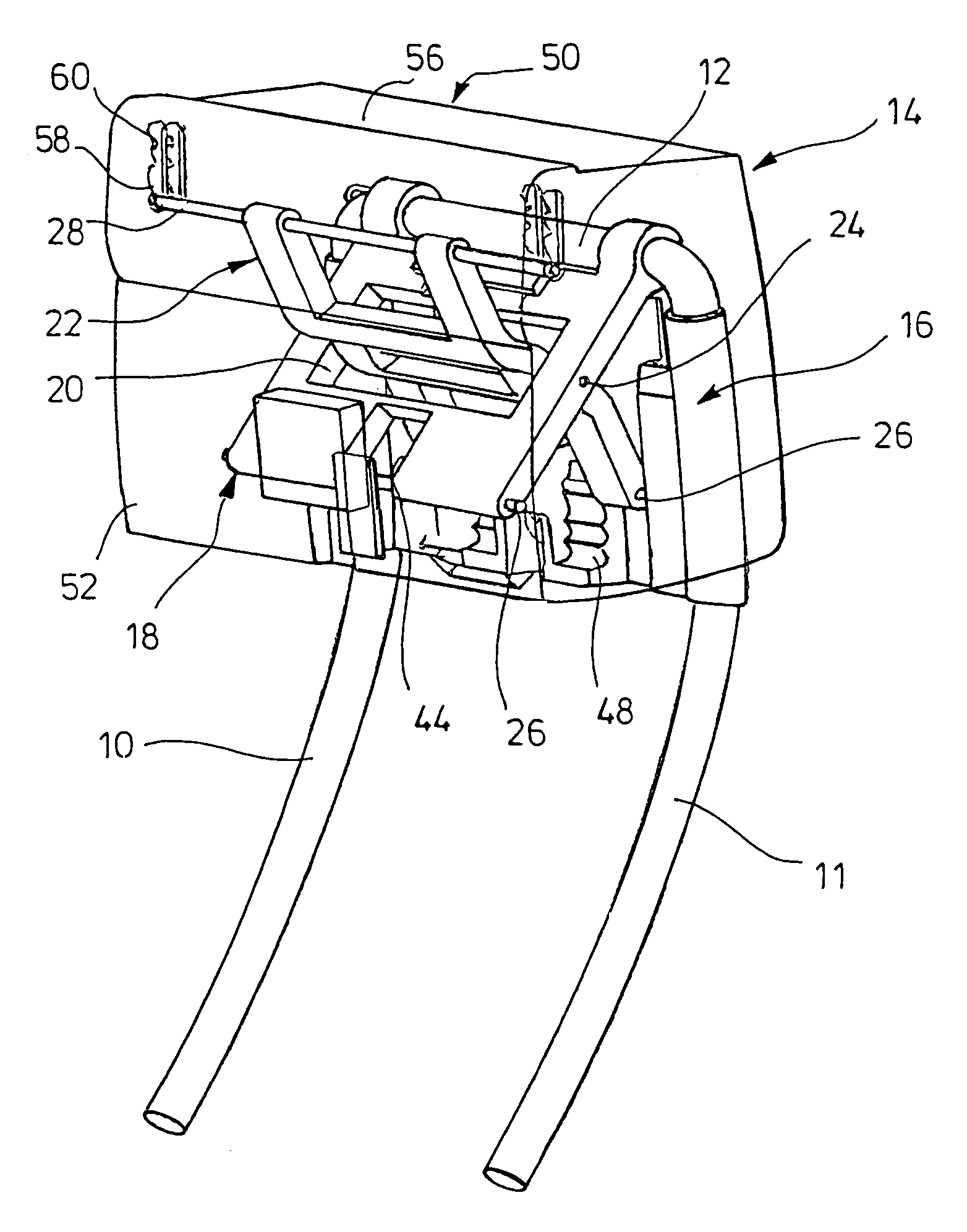
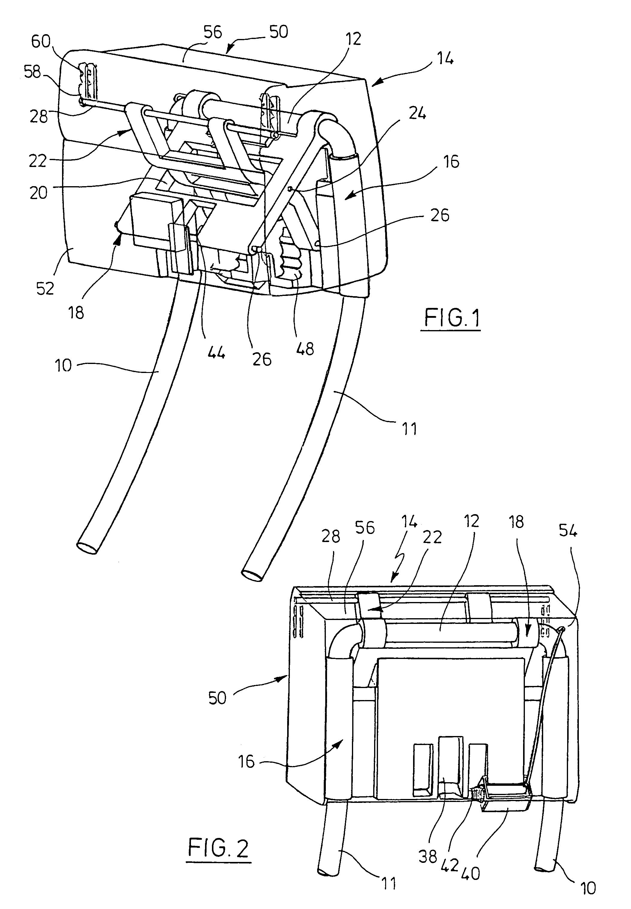
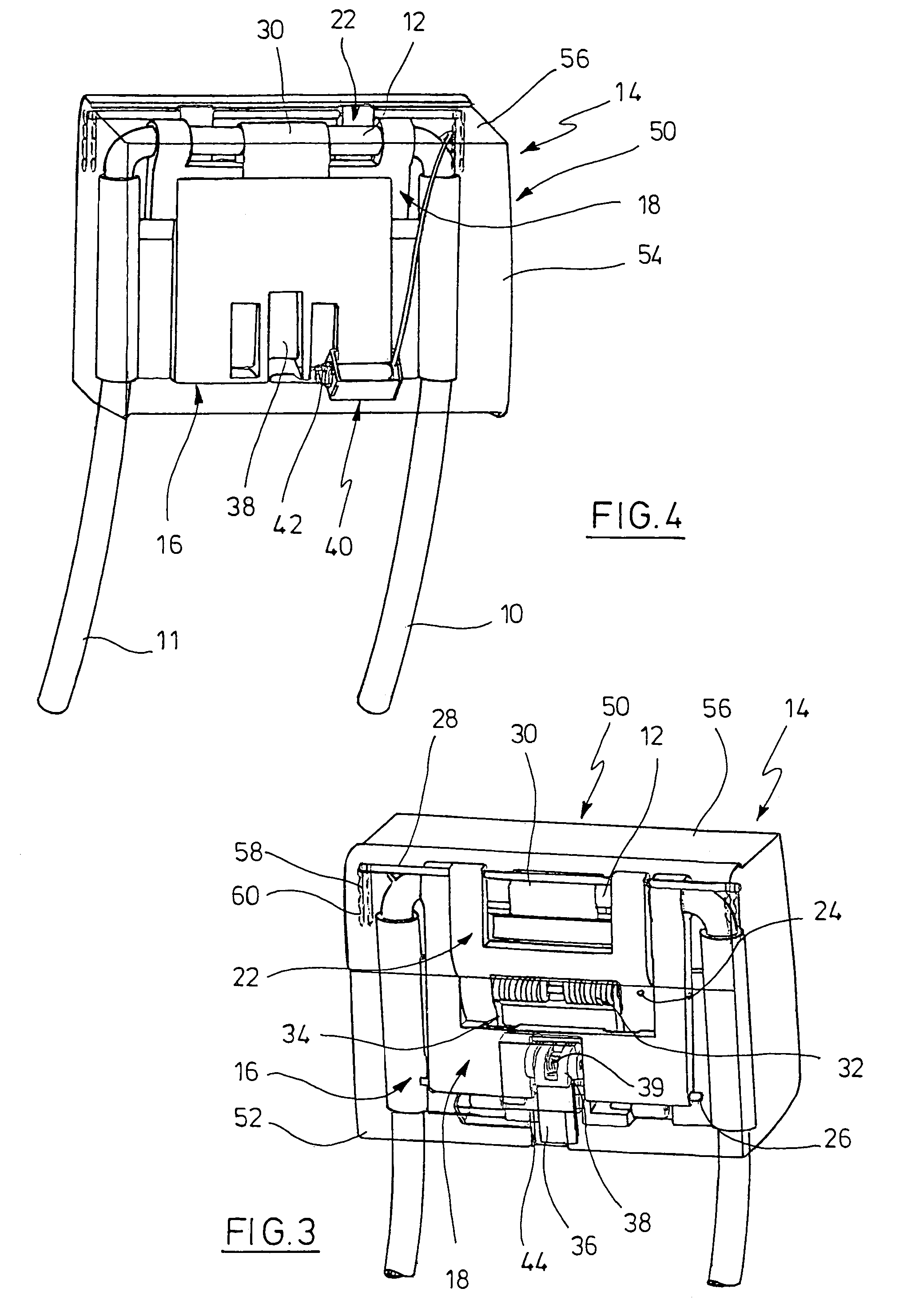
[0020]In FIGS. 1 through 4, two neck rest rods 10, 11 can be seen which are connected to each other via a transverse rod 12 at the upper end. The neck rest rods 10, 11 are received in appropriate receptacles in a back rest of an automobile seat which is not shown. The neck rest rods have mounted thereon a neck rest body 14 which will be described in detail below.

[0021]A plate-shaped support portion 16 is fixedly linked to the neck rest rods 10, 11 at the lateral ends and extends between these two ends below the transverse rod 12 interconnecting the rest rods 10, 11. A pivoting lever 18 is pivotally supported on the transverse rod 12, i.e. by means of two spaced bearing rings. The pivoting lever 18, which is relatively broad, has a first recess 20 (FIG. 1) and a second recess at the lower end. The recess 20 is traversed by a strut lever 22 which is pivotally supported in the middle of the recess as is outlined by the bearing pin 24 in FIGS. 1 and 3. The strut lever 22 has two paralle...


PUM


Abstract

A neck rest for a seat of an automobile has a neck rest body which includes a neck rest cushion and at least two neck rest rods connected with the neck rest body, the neck rest rods being accommodated in the back rest of the seat. Each of the neck rest rod has a support portion attached thereto. The neck rest body includes a housing which has a front wall and a rear wall, the cushion being attached to an outer side of the front wall and the rear wall, with the support portion being located in the housing between the front and the rear walls. The housing is moveable between a basic position and an extended position.

Description

RELATED APPLICATIONS[0001]The present application is based on, and claims priority from, German Application No. 10 2004 017 688.4, filed Apr. 10, 2004, the disclosure of which is hereby incorporated by reference herein in its entirety.FIELD OF THE INVENTION[0002]The invention relates to a neck rest for seats of automobiles according to claim 1.BACKGROUND OF THE INVENTION[0003]DE 199 61 617 A1; DE 199 51 966 A1 or DE 101 42 625 A1 have made known a neck rest which has a strut member which can be displaced towards the front on the seat user's head, and an impact member actuating the strut member. When there is an impact onto the rear end of the vehicle the impact member will be actuated and the strut member is displaced towards the front. The strut member is supported on the cushion holder via pivoting arms. In DE 199 51 966 A1, the strut member forms part of the neck rest cushion which consists of two components which are connected to each other via joints. The impact member can inte...

Claims


Application Information

Patent Timeline
Patent Type & Authority Patents(United States)
IPC IPC(8): A47C31/00A47C7/36B60N2/48B60R22/28
CPCB60N2/4885B60N2/4861B60N2/862B60N2/888
Inventor KLUHSPIES, RONALDFISCHER, GERDALBRACHT, CARSTEN
Owner ITW AUTOMOTIVE PRODS
Why Eureka
Try Eureka