Strap tension indicator for orthopedic brace

a technology of strap tension indicator and orthography, which is applied in the field of orthopaedic braces, can solve the problems of inability to modify and alternate construction of strap tension indicator, and achieve the effect of improving the stability and stability of the strap tension indicator

Active Publication Date: 2007-10-23
DJO
View PDF13 Cites 57 Cited by
  • Summary
  • Abstract
  • Description
  • Claims
  • Application Information

AI Technical Summary

Benefits of technology

[0008]The preferred embodiments of the present strap tension indicator for orthopedic brace have several features, no single one of which is solely responsible for their desirable attributes. Without limiting the scope of this strap tension indicator as expressed by the claims that follow, its more prominent features will now be discussed briefly. After considering this discussion, and particularly after reading the section entitled “Detailed Description of the Preferred Embodiments,” one will understand how the features of the preferred embodiments provide advantages, which include positive indication of strap tension, an unobtrusive, low-profile design that does not significantly alter the cosmetic appearance of the brace, the capability to be adjusted to provide tension indication for any brace strap regardless of the magnitude of the ideal tension for that particular strap, and very few moving parts, thus providing the indicator with a long life span.
[0010]Another preferred embodiment of the present strap tension indicator for orthopedic brace comprises a method of indicating the tension in a strap for an orthopedic brace. The method comprises the steps of providing an orthopedic brace having at least a first strap and a rigid brace member, providing on the rigid brace member an indicator, and applying tension to the strap. The first strap includes a strap tab that is secured to the rigid brace member and capable of moving with respect to the rigid brace member between a first position and a second position. The tension causes the strap tab to move from the first position to the second position, thereby altering an appearance of the indicator.

Problems solved by technology

This strap tension indicator is, however, susceptible to modifications and alternate constructions from that discussed above that are fully equivalent.

Method used


Image

  • Strap tension indicator for orthopedic brace
  • Strap tension indicator for orthopedic brace
  • Strap tension indicator for orthopedic brace

Examples


Embodiment Construction

,” one will understand how the features of the preferred embodiments provide advantages, which include positive indication of strap tension, an unobtrusive, low-profile design that does not significantly alter the cosmetic appearance of the brace, the capability to be adjusted to provide tension indication for any brace strap regardless of the magnitude of the ideal tension for that particular strap, and very few moving parts, thus providing the indicator with a long life span.

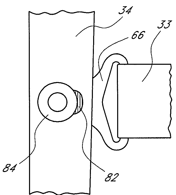
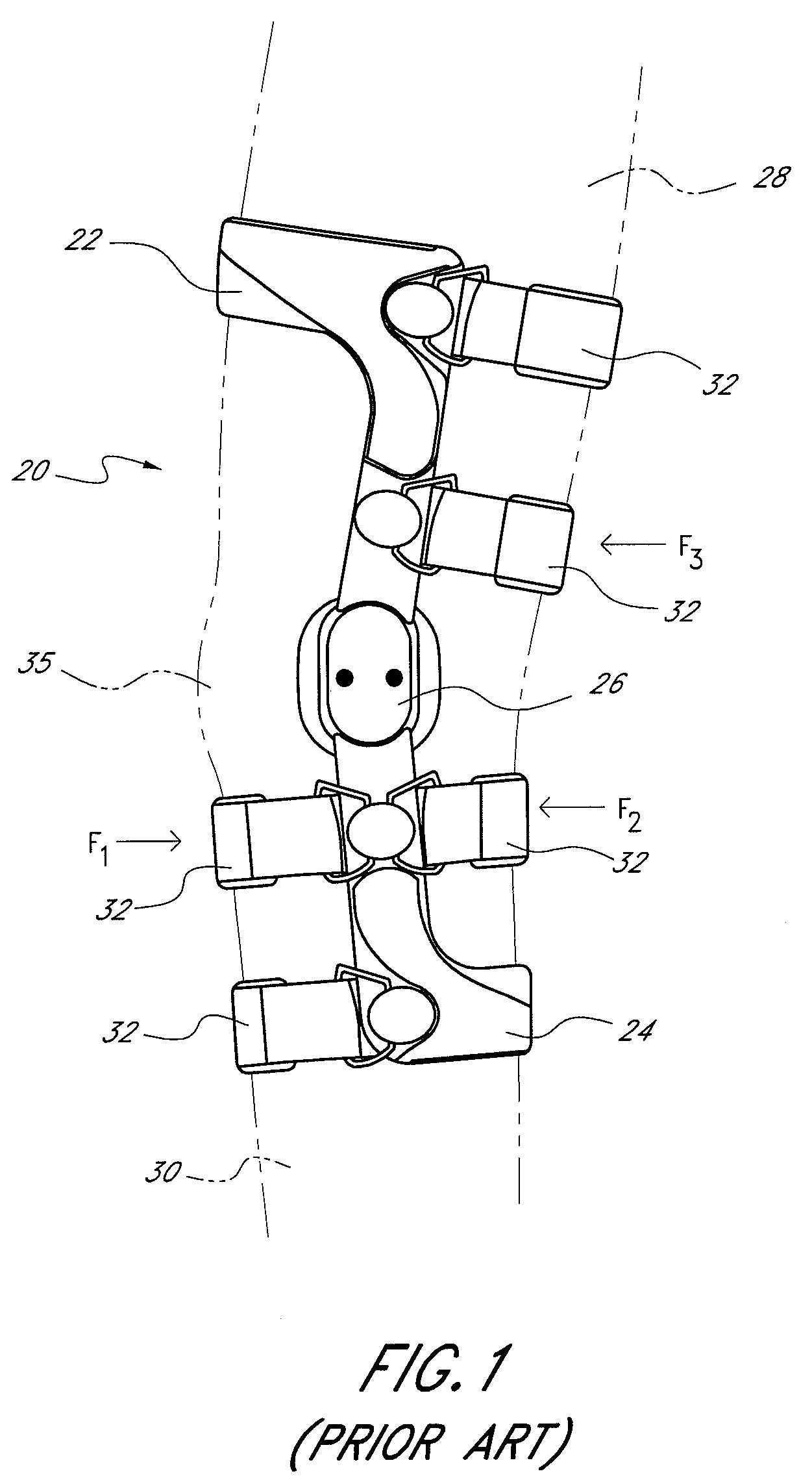
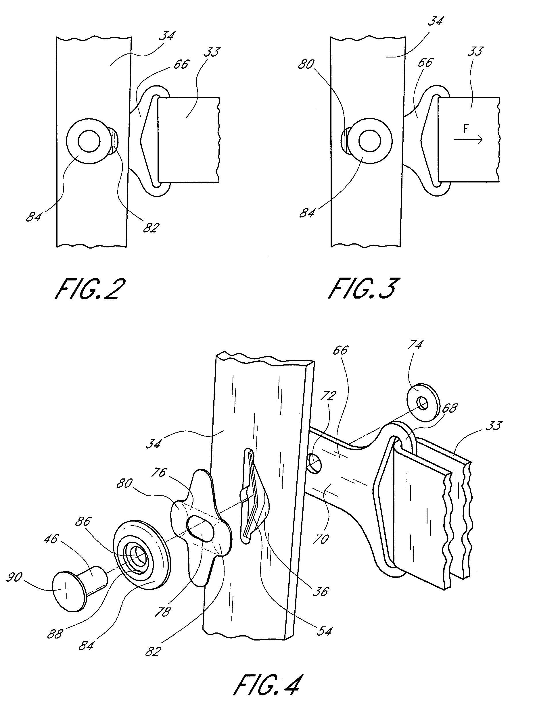
[0009]A preferred embodiment of the present strap tension indicator for orthopedic brace comprises a rigid brace frame member including an aperture, a resilient member located within the aperture, a strap tab and a fastening member cooperating with the aperture to secure the strap tab to the rigid brace member. In a first position, the fastening member abuts the resilient member. The strap tab and the fastening member are movable together toward a second position in which the resilient member tends to push the...


PUM


Abstract

A strap tension indicator for orthopedic brace is provided. Certain embodiments include a strap tab cap that is slidable relative to a rigid brace frame member. As tension in the strap increases or decreases, the strap tab cap slides with respect to the frame member, covering and uncovering various indicator portions on the frame member. Certain other embodiments include a strap tab that is slidable relative to a strap tab cap. As tension in the strap increases or decreases, the strap tab slides relative to the strap tab cap, covering and uncovering various indicator portions on the strap tab and / or the frame member. The strap tension indicator provides positive indication of optimal strap tension. Certain embodiments also provide positive indication of inadequate or excessive strap tension.

Description

BACKGROUND OF THE INVENTION[0001]1. Field of the Invention[0002]The present invention relates to orthopedic braces. More particularly, the present strap tension indicator for orthopedic brace provides a positive indication of optimal strap tension.[0003]2. Description of the Related Art[0004]Orthotic braces stabilize and protect joints, such as the knee. In many of these braces, straps fasten the brace to the limb and enable the brace to apply forces to the limb. The amount of tension in a strap affects the function, fit, and comfort of a brace. Inadequate tension can diminish the ability of the brace to stabilize or protect the limb, and can prevent the brace from staying in place on the limb. On the other hand, too much tension can cause discomfort for the wearer and restrict the wearer's blood flow. Therefore, orthotic brace wearers would benefit from a device that indicates whether the brace straps are properly tensioned for optimal function, fit, and comfort of the brace.[0005]...

Claims


Application Information

Patent Timeline
Patent Type & Authority Patents(United States)
IPC IPC(8): A61F5/00A44B19/00A61F5/01A61F5/02A61F13/00A61F13/04A61F13/06
CPCA61F5/01A61F13/048Y10T24/45246A61F2005/0179
Inventor NATHANSON, JEREMY J.
Owner DJO
Why Eureka
Try Eureka