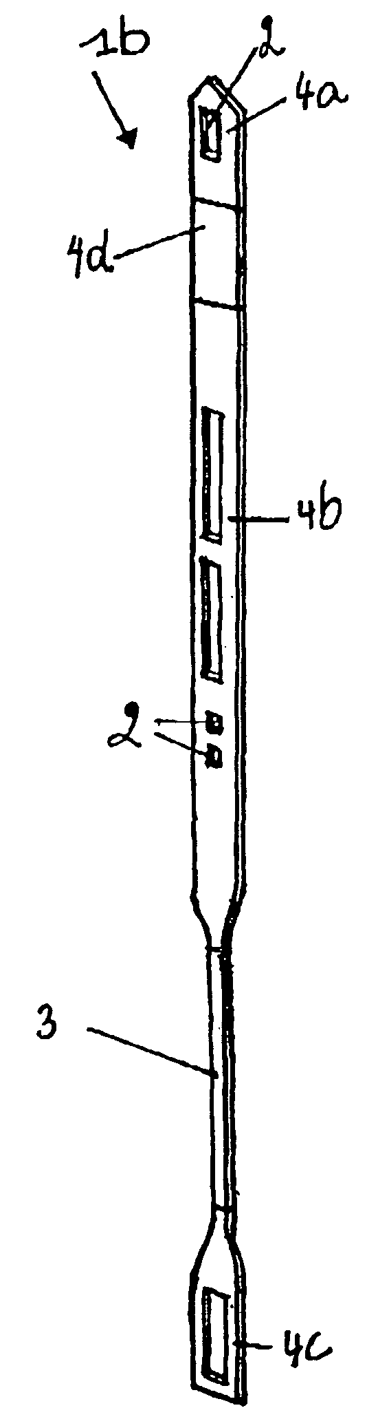
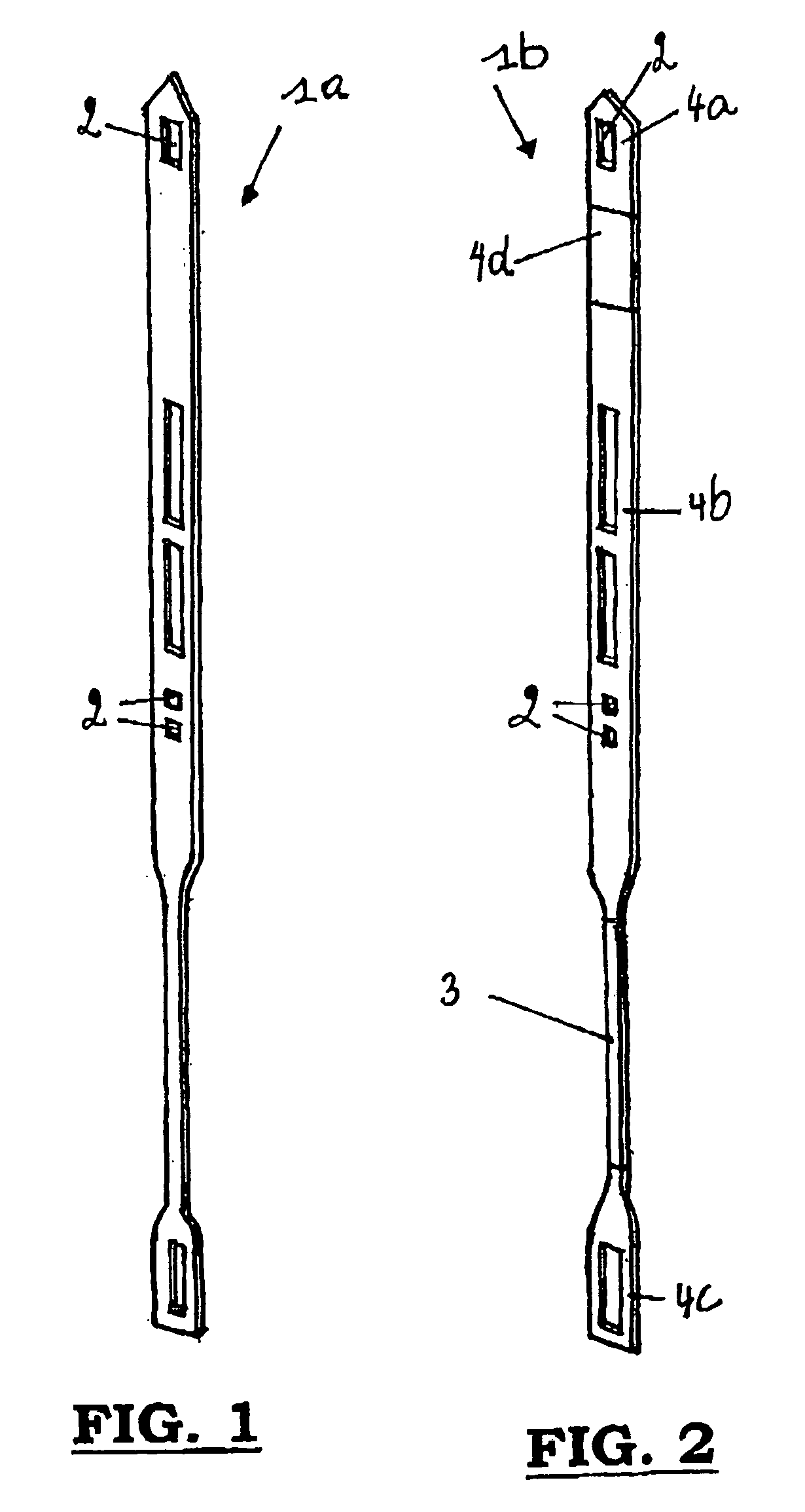
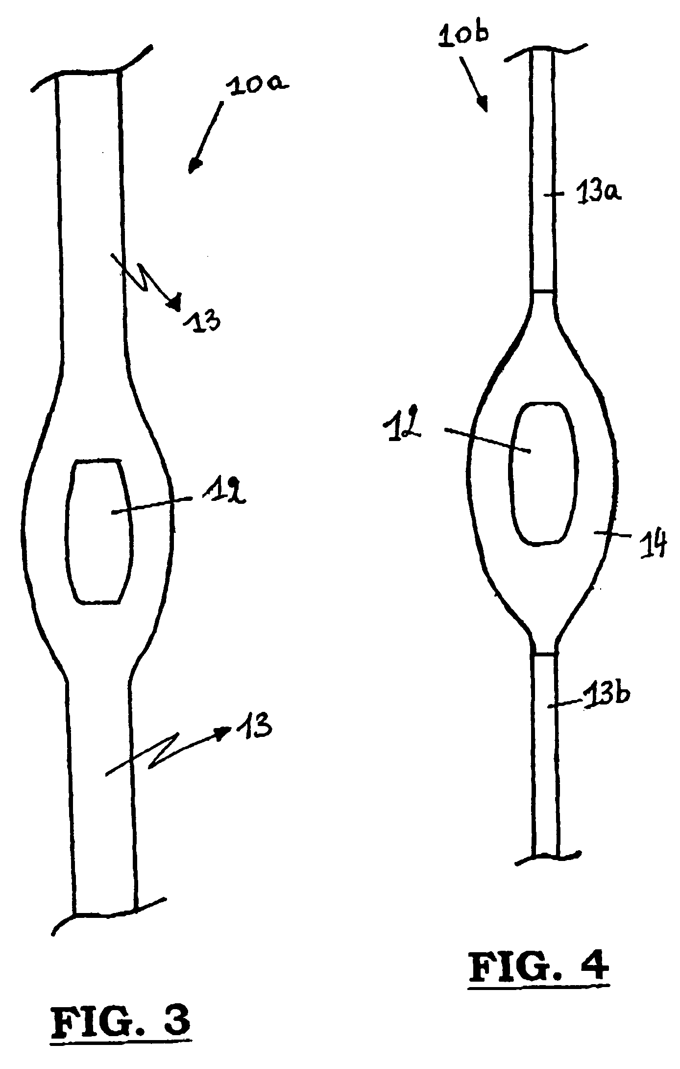
[0045]In a method according to the invention for manufacturing components consisting of one piece, appearing in weaving machines and comprising one or more different first parts, these parts are manufactured as separate parts and joined into a whole by means of processes which practically will not change the cross-sections of said parts. For each of the different parts of the component the most suitable design is produced or obtained according to the existing methods or channels in a condition, which will meet the necessary requirements.
[0046]The processes which practically do not change the cross-section of said parts are, for instance, resistance welding (=friction welding) or laser beam welding. By applying these processes, no finishing is required or only a limited finishing operation is required in the transition zone.
[0047]The different parts may have: [0048] different mechanical and/or magnetic and/or tribological properties; and/or [0049] different manufacturing methods; and/or [0050] different properties as to their shape.
[0051]By tribological properties is meant, for instance, being free of burrs, pure, polished, etc. Furthermore, these local parts may have specific requirements as to their shape, such as, for instance, recesses, deflections, local broadenings and others and/or combinations of these features.
[0052]More specifically, this method is applied when manufacturing long components. By long components, components are meant of about 0.4 to 2 meters long, where the local parts have a length being shorter than 0.3 meters.
These long components have
[0053] specific mechanical and/or magnetic and/or tribological properties and/or: [0054] specific requirements as to their shape; and/or [0055] a specific manufacturing method.
These requirements are more expensive compared to the other parts of the components which may be either manufactured in a very economic way of may be bought on the market having the necessary requirements, such as, among others, the tribological properties.
[0056]Therefore, the local parts are manufactured separately and provided with the necessary requirements, and then joined together by means of one of the processes mentioned above.
[0057]Some examples of such long components of weaving machines are:
[0058]Lancets:
[0059]In the Jacquard weaving process, lancets are used, or instance, to determine the height of the loops or to keep the upper and lower fabrics separated from one another in face-to-face weaving. These parts have to be fixed in a lancet holder, and they may be carried out in a stepped shape in order to be able to realize a variable intermediate height or they may be deflected in order to enable a adequate forming of the shed in, for instance, triple rapier weaving.
In consequence of these requirements, it is appropriate to use a manufacturing method such as stamping, which, according to the state of the art, should be used over the full length and after which the component has to be finished over its entire length.
[0060]When a method according to the invention is applied than the lancet is composed of: [0061] a first part, consisting of a stamped piece of material having an adequate shape, for instance, a stepped shape; [0062] a second part consisting of a strip having a cross-section corresponding to that of flat steel; and [0063] a third part, consisting of a stamped piece of material, designed to be fixed in the lancet holder.
Hooks:
[0064]A hook (1a, 1b) as represented in the FIGS. 1 and 2, is used in the Jacquard part of a Jacquard weaving machine by coupling it or not to the blades moving up and down in order to bring the coupled, pattern forming pile warp yarns in their exact position in the shed. Therefore the hooks (1a, 1b) are provided with recesses (2) in order to overmould the hook with synthetic material hooking onto the blades or to overmould the nose hooking onto the selector housing, by means of extrusion. For this purpose, the hook (1a) according to the state of the art, as shown in FIG. 1 is stamped, over its entire length, from spring steel, which is chosen as a compromise in order to comply with the various functional requirements of the hook (1a). The entire hook (1a) is made, for instance, of spring steel having lower magnetic properties, but higher elastic properties, thus allowing the hook (1a) to be drawn against the selector housing.
[0065]In a hook (1b) according to the invention, as shown in FIG. 2, the non-functional part (3) is made of flat steel, available on the market, which is sufficiently pure. The functional parts (4a, 4b, 4c, 4d) are made according to the most suitable design.
[0066]So, the component is composed of: [0067] a first part (4a) consisting of a stamped piece of material, which may be covered by overmoulding; [0068] a second part (4d) consisting of a flat piece of material having adequate magnetic properties, so that it may be influenced by a magnetic selector; [0069] a third part (4b) consisting of a stamped piece of spring steel; [0070] a fourth part (3) consisting of a flat piece of material available on the market; and [0071] a fifth part (4c) consisting of a stamped piece of material.
Heddles:
[0072]A heddle (10a, 10b), as partly represented in the FIGS. 3 and 4, comprises a guide eye (12) which has to guide one or more warp yarns to bring them into the position required with respect to the shed.
[0073]A flat steel heddle (10a) according to the state of the art, as shown in FIG. 4 is made in one piece. The requirements demanded from the guide eye (2) require a manufacturing method such as stamping which, according to the state of the art, should be used over its entire length. Then an expensive operation to finish the part will be necessary.
[0074]When the guide eye (12) is left out of account, the function of the remaining parts (13) of the heddle (10a) shown, may be entirely taken over by a wire or even by flat steel, both available on the market.
[0075]The second part (4) in which the eye of the heddle is provided, should rather be made of a wear-resistant material, because it should be capable of resisting the wear and tear caused by the warp yarns which are guided through it, whereas the heddle wire parts (3a, 3b) should be made of a material having rather flexible properties, because they must be able to react to the tensions in the warp yarn in the warp direction.
[0076]As shown in FIG. 4, the heddle (10b) according to the invention is composed of: [0077] a first part (3a) made of wire material (or flat steel); [0078] a second part (4) consisting of a stamped piece of material; and [0079] a third part (3b) made of wire material.
[0080]Preferably, one end or both ends of the stamped part or the second part (4) ends in a shape having a cross-section corresponding to the cross-section of the first (3a) and/or the third part (3b) (for instance, wire or flat steel).
[0081]Therefore this invention may be applied to long components as well, which are used in weaving machines.