
Yagi antenna with balancing tab

a technology of balancing tab and antenna, which is applied in the direction of antennas, electrically long antennas, electrical apparatus, etc., can solve the problems of large antenna bulge, mechanical and electrical disadvantages, and serious deformation of antenna gain and radiation pattern, so as to reduce antenna cost, reduce antenna cost, and reduce radiation

Active Publication Date: 2007-10-23
WILSON ELECTRONICS
View PDF5 Cites 9 Cited by
  • Summary
  • Abstract
  • Description
  • Claims
  • Application Information

AI Technical Summary

Benefits of technology

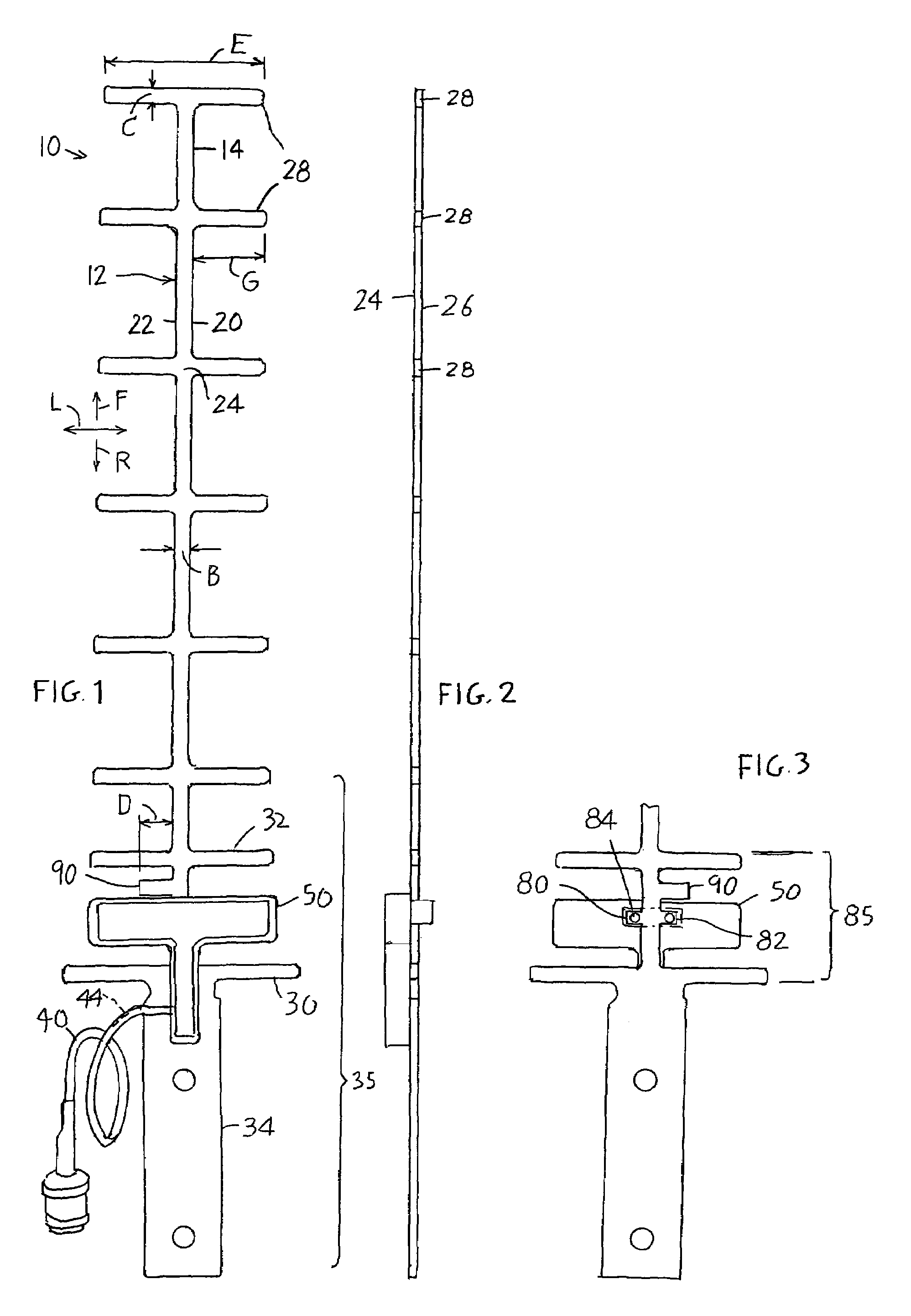
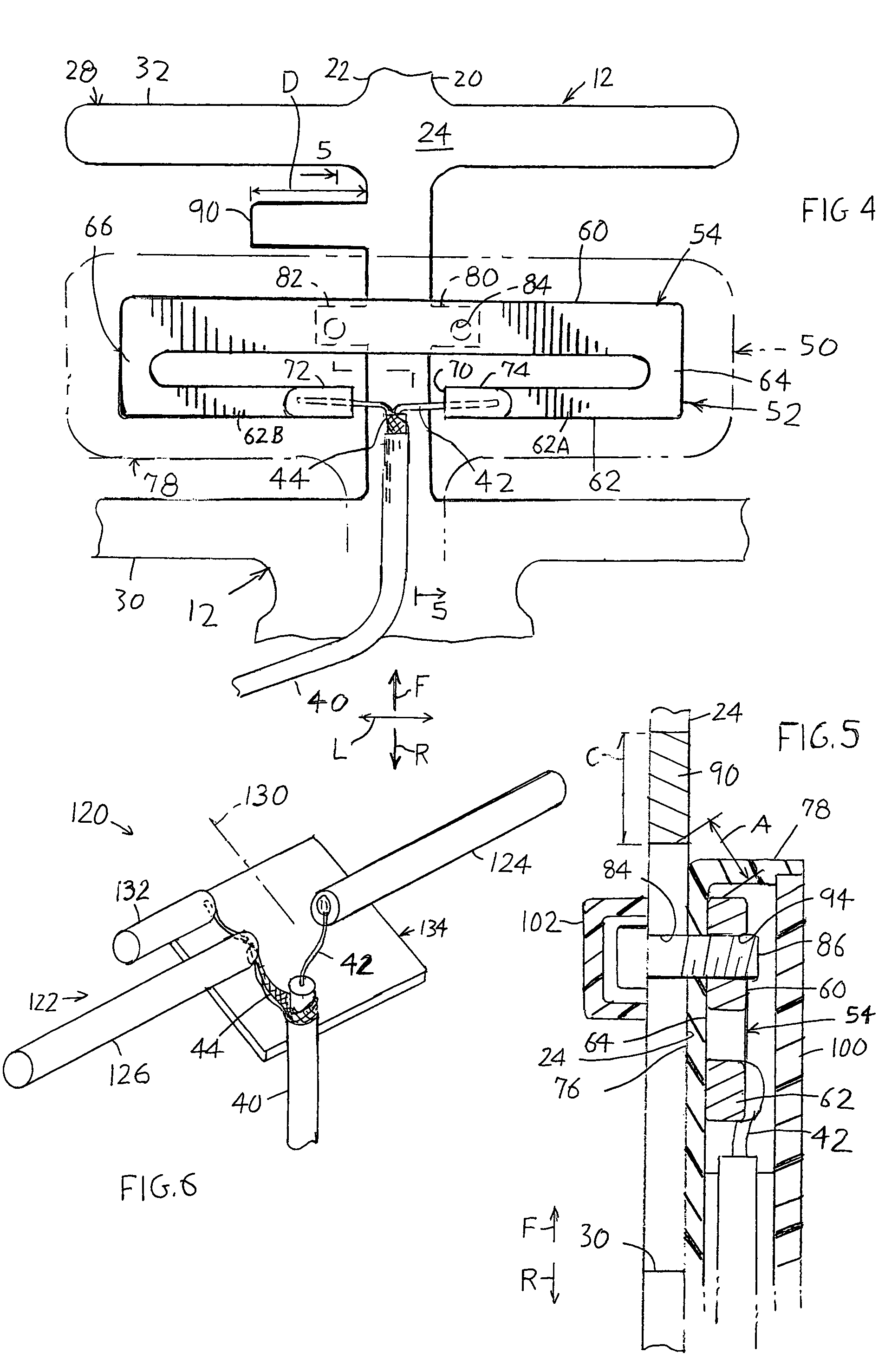
[0002]In accordance with one embodiment of the present invention, an antenna, and in particular a Yagi antenna, is provided which minimizes radiation from a transmission line such as a coaxial cable that carries signals to or from the antenna, in a manner that avoids the need for a balun, to thereby reduce the cost of the antenna and make it more compact and efficient. A Yagi antenna is provided of the type that has a flat Yagi structure, with a boom that extends in front and rear directions and with a plurality of directors that extend laterally across the boom. The antenna is improved by providing a balancing tab that extends laterally from one side of the boom. A coaxial cable is coupled to the Yagi structure by an electrical coupling that includes a folded dipole formed by a metal plate. The metal plate is mounted on a dielectric separator that lies facewise adjacent to a rear portion of the Yagi structure. The metal plate forms a loop having laterally long front and rear loop parts, the rear loop part having a gap. The inner and outer coax conductors are connected to the rear loop part at opposite sides of the gap. The balancing tab lies a short distance forward of the front loop part, on the same side of the boom as the side of the gap to which the coax cable outer conductor is connected.
[0003]The metal plate that forms the loop, and the separator, can be mounted on the Yagi structure by a pair of simple screws, and the metal plate that forms a loop projects only slightly from the plane of the Yagi elements. This results in a simple and easily constructed antenna that is compact.

Problems solved by technology

A transmission line such as a coaxial cable, which is connected to an antenna such as a Yagi antenna, may radiate energy that seriously degrades both the gain and radiation pattern of the antenna.
A balun is basically a wire wound transformer or a specially connected distributed transmission line, and results in mechanical and electrical disadvantages.
A mechanical disadvantage is that the balun must be protected from moisture and from exposure to the sun, and the balun can be a bulky part that produces a large bulge in the antenna.
An electrical disadvantage is that the balun introduces losses, thereby reducing antenna gain and therefore its efficiency.
The balun also increases manufacturing cost.

Method used


Image

  • Yagi antenna with balancing tab
  • Yagi antenna with balancing tab
  • Yagi antenna with balancing tab

Examples


Embodiment Construction

[0011]FIGS. 1-3 illustrate a Yagi antenna 10 (named after the inventor, Yagi Hidetsuga) which is a highly directional antenna for electromagnetic radiation, with the particular antenna illustrated having been constructed for use in the 1900 MHz cell phone frequency band. The Yagi antenna includes an electrically conductive Yagi structure 12 having an elongated boom 14 that is elongated in front and rear directions F, R and that has laterally L opposite boom sides 20, 22 and opposite boom faces 24, 26. The Yagi structure also has a plurality of directors 28 that are each elongated in the lateral directions L and that each extends across the boom and that each has parts of equal length on laterally opposite sides of the boom. The Yagi structure also includes a reflector 30 that lies rearward of the directors 28 and that generally has a greater lateral length than the directors. The antenna radiates power in the forward direction F and receives radiation moving in the rearward directio...


PUM


Abstract

An antenna minimizes radiation from the outer conductor (44) of a coaxial cable (40) that is coupled to the antenna by providing a balancing tab (90) that lies near the connection (72) of the cable outer conductor (44) to the antenna. One antenna includes a Yagi structure (12) constructed of a plate of metal that forms a long boom (20) and a plurality of directors (28) extending laterally across the boom, with an electrical coupling loop mounted at a rear region of the Yagi structure. The coupling loop includes a folded dipole in the form of a metal coupling plate that forms a loop (54) with a gap (70), the loop having a laterally elongated front loop end (60). The Yagi structure is formed with a balancing tab (90) that lies forward of the loop, that has a lateral length (D) less than half that of one of the directors, and that extends from only one side (22) of the boom which is the side to which the outer coax conductor (44) is connected to the loop. The metal coupling plate lies facewise adjacent to a face (24) of the Yagi plate, with a dielectric spacer (76) between them.

Description

BACKGROUND OF THE INVENTION[0001]A transmission line such as a coaxial cable, which is connected to an antenna such as a Yagi antenna, may radiate energy that seriously degrades both the gain and radiation pattern of the antenna. Ideally, equal and opposite currents flow from the coaxial cable into the terminals of a balanced antenna. However, in practice, energy radiates from the outer conductor (the shield) of the coaxial cable. A common technique used to minimize such radiation is to connect a balun (which stands for “balanced to unbalanced”) in the circuit which forces the coaxial cable to feed equal and opposite currents into the antenna. A balun is basically a wire wound transformer or a specially connected distributed transmission line, and results in mechanical and electrical disadvantages. A mechanical disadvantage is that the balun must be protected from moisture and from exposure to the sun, and the balun can be a bulky part that produces a large bulge in the antenna. An ...

Claims


Application Information

Patent Timeline
Patent Type & Authority Patents(United States)
IPC IPC(8): H01Q21/00H01Q11/04H01Q19/00H01Q19/30H01Q21/12
CPCH01Q19/30
Inventor VAN BUREN, ALANKLINE, RICHARD M.
Owner WILSON ELECTRONICS
Learn More