Soft-switching power converter having power saving circuit for light load operations

a power saving circuit and soft-switching technology, applied in the direction of electric variable regulation, process and machine control, instruments, etc., can solve the problems of electrical interference, component stress, electrical interference, etc., and achieve the effect of reducing power consumption

Active Publication Date: 2007-10-23
SEMICON COMPONENTS IND LLC
View PDF6 Cites 62 Cited by
  • Summary
  • Abstract
  • Description
  • Claims
  • Application Information

AI Technical Summary

Benefits of technology

[0012]The objective of the invention is to provide a soft switching power converter to reduce power consumption under light load conditions.

Problems solved by technology

However, the switching losses, the component stresses, and electromagnetic interference (EMI) are the inherent problems.
Although the aforementioned power converters are able to achieve soft switching operation to reduce the switching loss under heavy load conditions, the drawback, however, is higher power consumption under light load conditions.

Method used


Image

  • Soft-switching power converter having power saving circuit for light load operations
  • Soft-switching power converter having power saving circuit for light load operations
  • Soft-switching power converter having power saving circuit for light load operations

Examples


Embodiment Construction

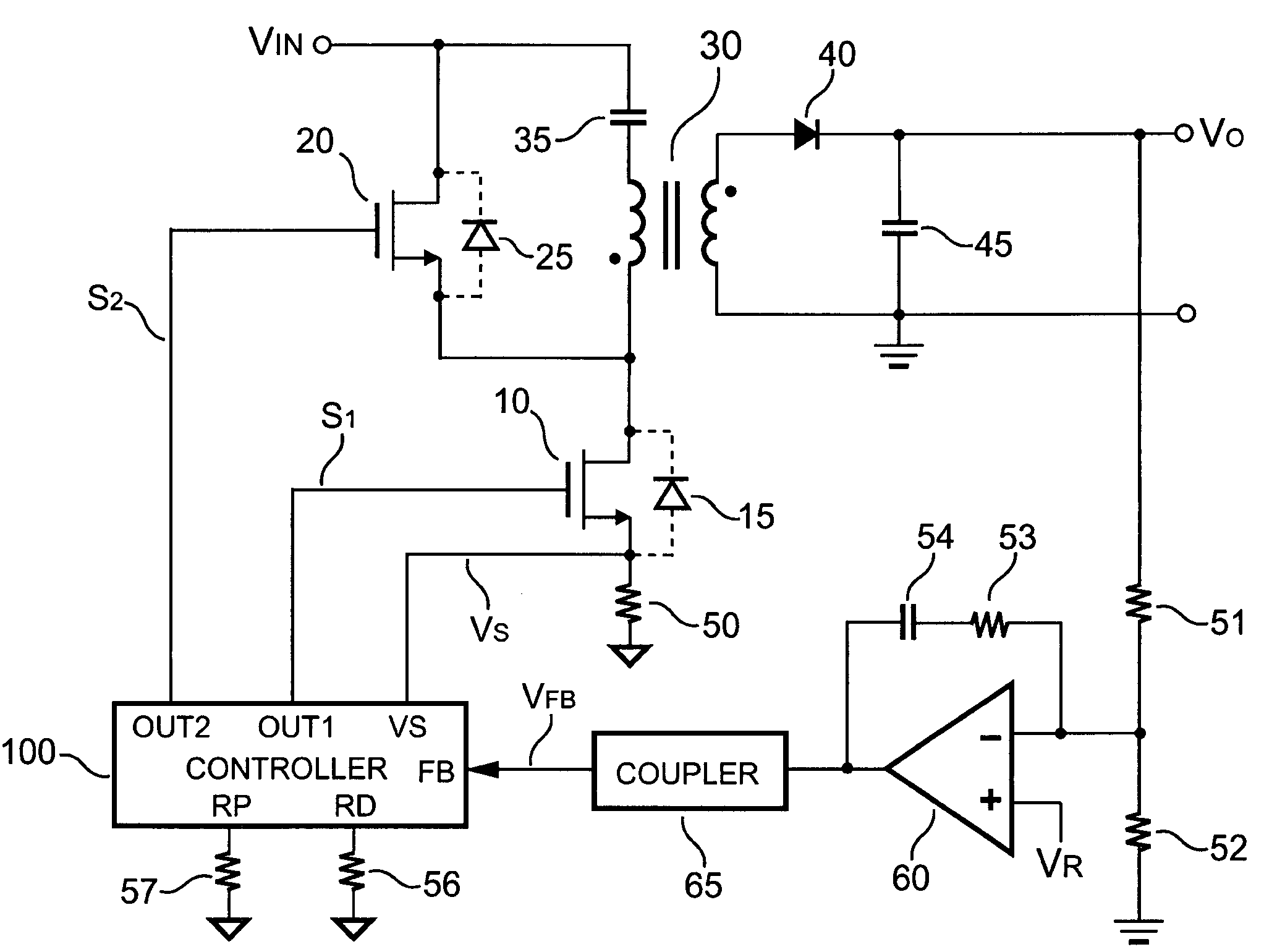
[0023]FIG. 3 is a schematic circuit of a soft switching power converter according to an embodiment of the present invention. It includes a magnetic device, such as a transformer 30. The transformer 30 is connected with a capacitor 35 in series. The capacitor 35 is used for soft switching operation. A first switch 10 is utilized for switching the transformer 30 to transfer the energy from an input of the power converter to an output of the power converter. A second switch 20 is coupled for switching the capacitor 35 to transfer the energy of the capacitor 35 to the transformer 30. A control circuit 100 is coupled to the output of the power converter to generate a first signal S1 and a second signal S2 in response to a feedback signal VFB for regulating the output of the power converter. The first signal S1 and the second signal S2 are coupled to switch the first switch 10 and the second switch 20, respectively. An error amplifier 60 having a reference signal VR is connected to the ou...


PUM


Abstract

A soft switching power converter includes a first switch for switching a transformer to transfer energy. A second switch is equipped to switch energy in a capacitor to the transformer to achieve soft switching for the next switching cycle. A control circuit is coupled to an output of the power converter for generating a first signal and a second signal in response to a feedback signal for regulating the output of the power converter. A first delay time is generated after the first switch is turned off and before the second signal is on. A second delay time is generated after the second switch is turned off and before the first signal is on. The second delay time is increased corresponding to a decrement of the feedback signal under light load conditions.

Description

BACKGROUND OF THE INVENTION[0001]1. Field of the Invention[0002]The present invention relates to power converters, and more particularly to the control circuit of power converters.[0003]2. Description of the Related Art[0004]Power converters are used for converting an unregulated power source to a constant voltage source. Power converters generally include a transformer having a primary winding and a secondary winding for providing the isolation. The switching devices are connected to the primary winding for controlling the energy transfer from the primary winding to the secondary winding. A higher operating frequency allows a reduced size and weight for power converters. However, the switching losses, the component stresses, and electromagnetic interference (EMI) are the inherent problems. In recent developments, a popular phase-shift scheme for soft switching has been proposed for high frequency power conversion for reducing switching losses. Among them, the full-bridge (FB) quasi...

Claims


Application Information

Patent Timeline
Patent Type & Authority Patents(United States)
IPC IPC(8): H02M3/335H02M3/22
CPCH02M3/33569
Inventor YANG, TA-YUNG
Owner SEMICON COMPONENTS IND LLC
Why Eureka
Try Eureka