AI technical title is built by PatSnap AI team. It summarizes the technical point description of the patent document.
a manufacturing control and automatic technology, applied in the field of industrial automation, can solve the problems of large flat area, inability to apply barcode labels on raw materials, and inability to meet the requirements of outgoing production, and achieve the goal of complete automation of reading operations
Inactive Publication Date: 2007-10-23
COGISCAN
View PDF38 Cites 53 Cited by
Summary
Abstract
Description
Claims
Application Information
AI Technical Summary
This helps you quickly interpret patents by identifying the three key elements:
Problems solved by technology
Method used
Benefits of technology
Benefits of technology
[0025]It is therefore an aim of the present invention to provide a novel method for globally monitoring and controlling a number of parameters of a manufacturing process.
[0047]In accordance with a more specific aspect of the present invention, there is provided a system which greatly reduces the human interaction relative to the data transfer, physical verification and process control associated with the movement of components, tooling and operators in a manufacturing system.
Problems solved by technology
All these elements will have to be prepared and, if an error occurs and a wrong element is used or the wrong information about it is entered, the outgoing production will not conform to the specifications.
This yields an inventory that relies highly on human interventions and that is always outdated as it is not in real-time.Process control.
One general drawback of using barcodes is the need of a sufficiently large flat area to apply a barcode label which is not always available on raw material, its container, or other parts to be traced.
This can be a major restriction toward complete automation of the reading operation.
Finally, barcodes offer a limited number of information that can be written only once (at the printing operation of the barcode) and thus that cannot be altered.
In a manufacturing environment, this is significant since it may be impractical to have all machines and manufacturing systems connected to a single network and central database.
Due to the higher cost of the RFID tags compared to barcode labels, this application uses mostly barcodes.
Although the above described monitoring systems are useful, they are only adapted to perform a single task.
Method used
Image
Click on the blue label to locate the original text in one second.
Reading with bidirectional positioning of images and text.
Examples
1st example
1st Example
Transponders on Reels and Trays
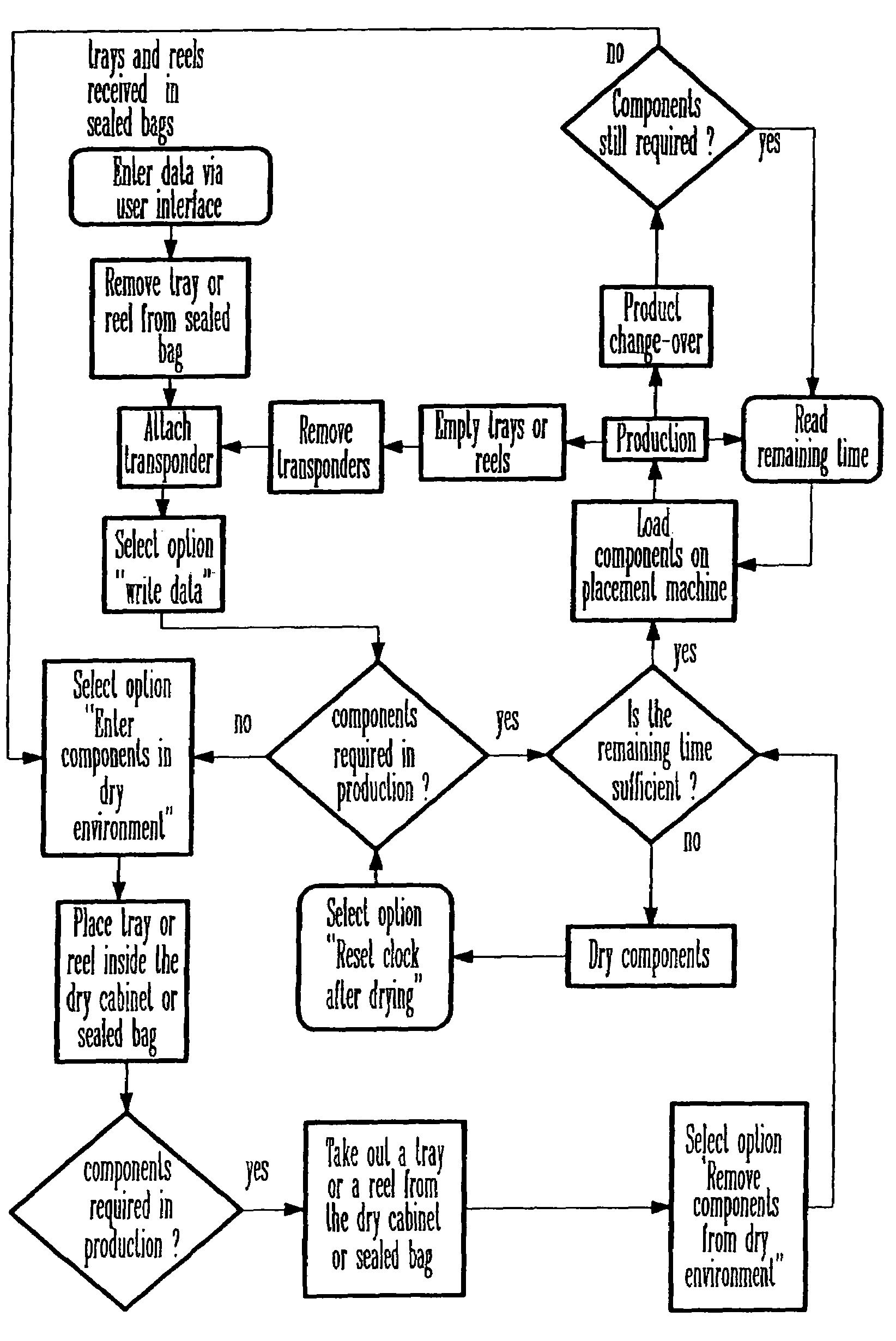
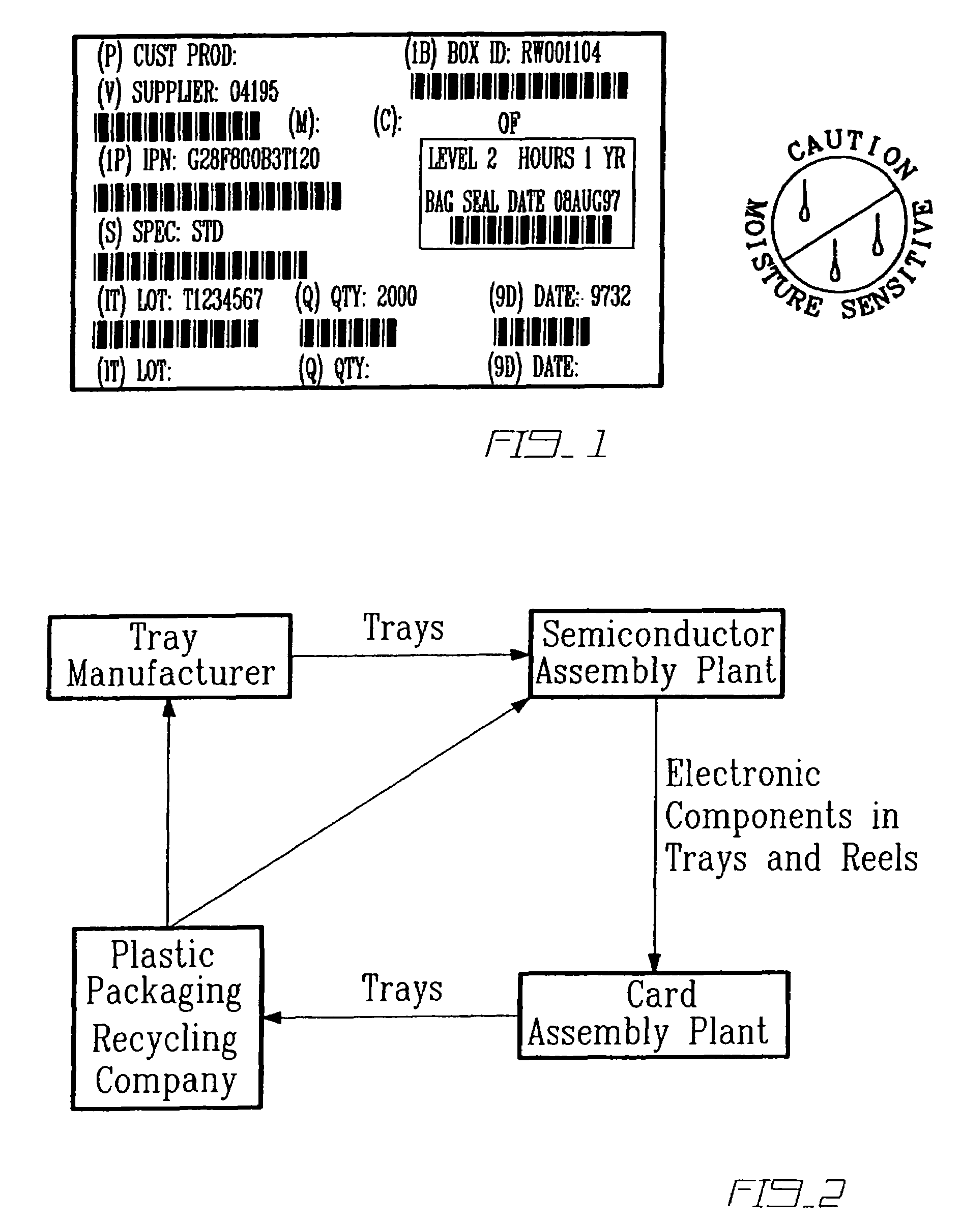
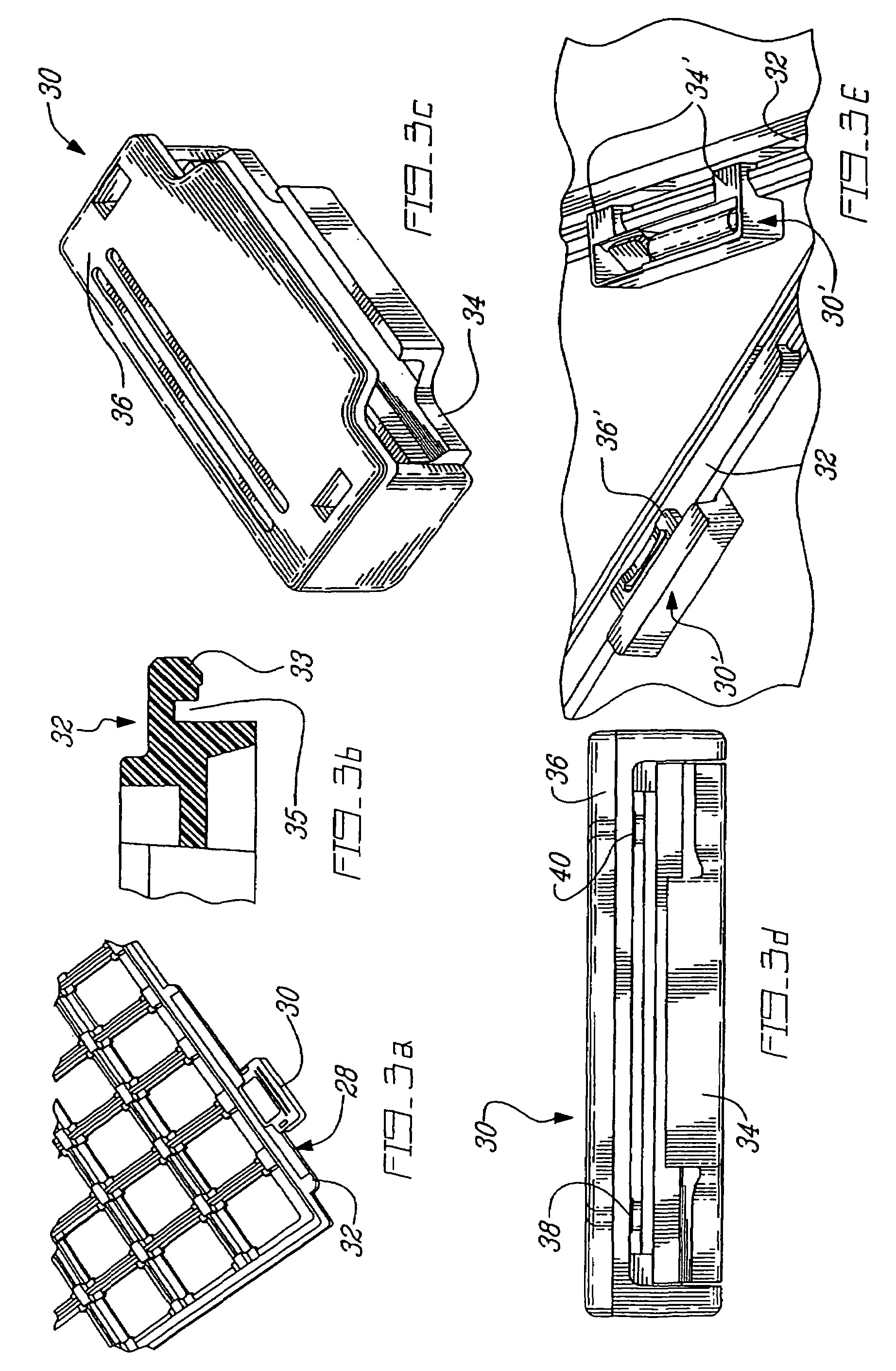
[0096]Given the existing infrastructure of barcode identification and the relatively high unit cost of a typical transponder, the present example is based on the use of a temporary means to attach the transponder, with different designs adapted to each format of packaging. In this case, the transponders 12 (i.e. the chip and the coupling element) are used in a closed loop cycle. For this reason, the benefits of the system must be more important that the additional cost associated with the attachment and removal of the transponders 12, including the initial data entry. Any application would become even more advantageous if the card assembly plant can receive the reels and trays (FIGS. 3a and 3f) from its suppliers with the transponders 12 already attached thereto and with the data already present in the proper format.
[0097]In this application, it is important that the shape and location of the transponders 12 do not affect the normal handling...
PUM
Abstract
An automated manufacturing control system is proposed to greatly reduce the human interaction relative to the data transfer, physical verification and process control associated with the movement of components, tooling and operators in a manufacturing system. This is achieved by the use of data carriers which are attached to the object(s) to be traced. These data carriers (12) can store all the relevant identification, material and production data required by the various elements, e.g. stations, of the manufacturing system. Various readers, integrated with controllers and application software, are located at strategic points of the production area, including production machines and storage areas, to enable automatic data transfer and physical verification that the right material is at the right place at the right time, using the right tooling.
Description
CROSS REFERENCE TO RELATED APPLICATIONS[0001]This application is a Continuation of U.S. application Ser. No. 10 / 257,401 filed on Oct. 21, 2002 (now U.S. Pat. No. 7,069,100 B2, which issued on Jun. 27, 2006) which is a National Entry Application of PCT Application No. PCT / CA01 / 00559 filed on Apr. 20, 2001, which itself claims priority on Canadian Applications No. 2,306,304 filed on Apr. 20, 2000, No. 2,321,009 filed on Sep. 27, 2000, No. 2,326,218 filed on Nov. 17, 2000 and No. 2,326,301 filed on Nov. 17, 2000. All documents above are herein incorporated by reference.FIELD OF THE INVENTION [0002]The present invention relates to industrial automation and, more particularly, to a system and method for controlling and monitoring a manufacturing process.BACKGROUND OF THE INVENTION [0003]In a manufacturing system, in order to deliver the finished goods, a lot of elements have to be moved on the production floor from time to time as they are required in different locations. Most of these m...
Claims
Application Information
Patent Timeline
Application Date:The date an application was filed.
Publication Date:The date a patent or application was officially published.
First Publication Date:The earliest publication date of a patent with the same application number.
Issue Date:Publication date of the patent grant document.
PCT Entry Date:The Entry date of PCT National Phase.
Estimated Expiry Date:The statutory expiry date of a patent right according to the Patent Law, and it is the longest term of protection that the patent right can achieve without the termination of the patent right due to other reasons(Term extension factor has been taken into account ).
Invalid Date:Actual expiry date is based on effective date or publication date of legal transaction data of invalid patent.

